Door mirror

a technology for door mirrors and mirrors, applied in the field of door mirrors, can solve the problems of increasing the need for lamp replacement, shortened lamp life, and failure of light, and achieve the effect of easy replacemen

Inactive Publication Date: 2010-03-25
MURAKAMI CORP
View PDF7 Cites 9 Cited by
  • Summary
  • Abstract
  • Description
  • Claims
  • Application Information

AI Technical Summary

Benefits of technology

[0013]According to the present invention, the lamp incorporated in the door mirror can be replaced easily.

Problems solved by technology

A lamp reaching the end of its life causes a lighting failure generated by filament breakage.
Particularly, the life of the lamp tends to be shortened by vibration or shock of a moving vehicle, which increases the need for lamp replacement.

Method used


Image

  • Door mirror
  • Door mirror
  • Door mirror

Examples


Embodiment Construction

[0041]Preferred embodiments of the door mirror according to the present invention are now described hereinafter in detail with reference to the drawings.

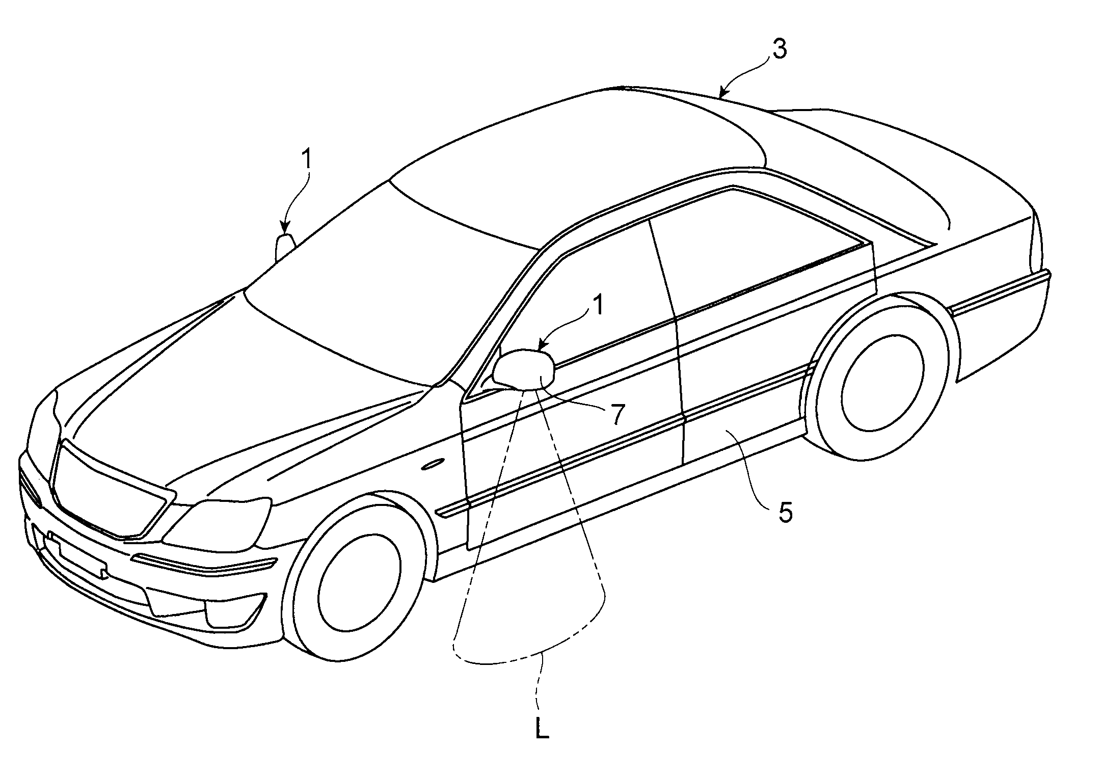
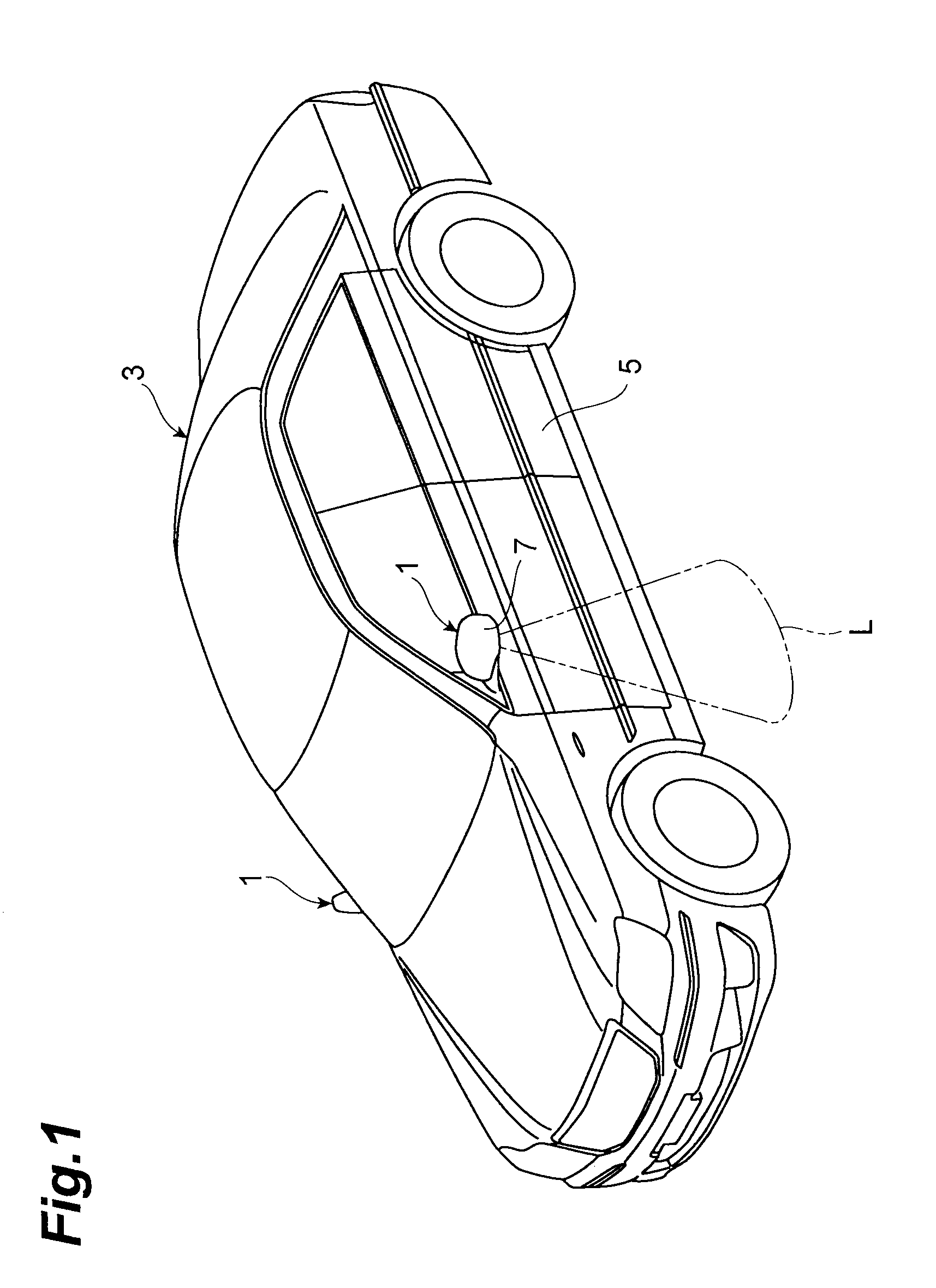
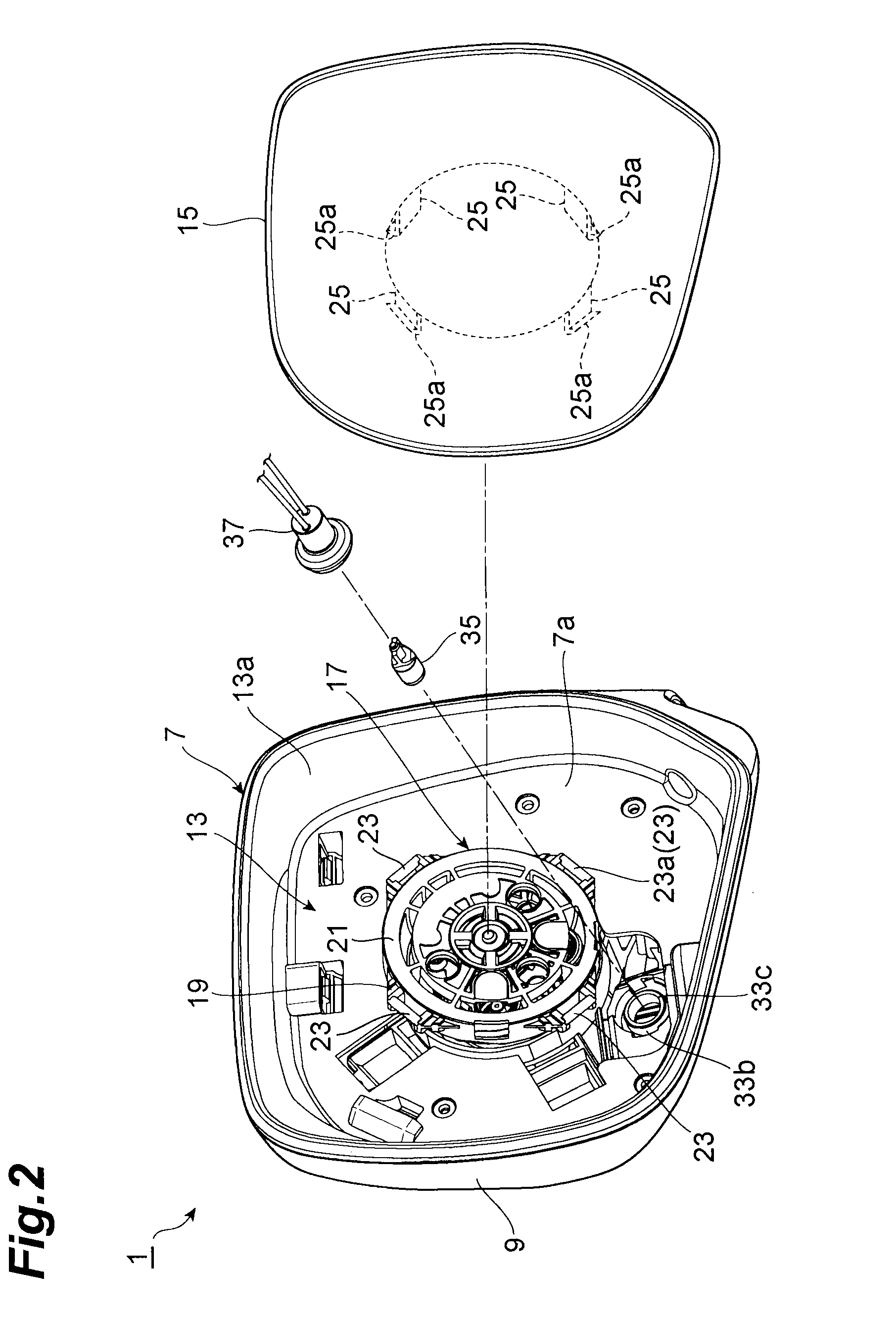
[0042]As shown in FIGS. 1 and 2, a door mirror 1 is fixed to a door 5 of a vehicle 3 and has a door mirror body 7 made of resin. This cup-shaped door mirror body 7 has a casing 9 that has an opening 9a (see FIG. 4) fixed to the door 5 and opened to a rear part side of the vehicle 3, and a cup-shaped partition plate 13 fitted and fixed to the opening 9a of the casing 9.

[0043]As shown in FIGS. 2 and 3, a plate-like holder / mirror assembly (mirror part) 15 is disposed to close a concave part 13a of the partition plate 13, that is, an opening 7a of the door mirror body 7. An opening part 19 for exposing a pivot plate 17 is formed in the center of the partition plate 13.

[0044]The pivot plate 17 has a circular plate part 21 abutted on a back surface of the holder / mirror assembly 15 and four retaining parts 23 provided at an outer circumfer...


PUM


Abstract

Light of an incorporated lamp illuminates the lower side of a side surface of a door of a vehicle. A rear end part of a lamp socket mounted with the lamp is exposed from a cylinder part of a lamp housing and projected from the lamp housing toward a holder / mirror assembly. Therefore, when replacing the lamp, the lamp socket can be found easily by simply removing the holder / mirror assembly, and the lamp can easily be extracted along with the lamp socket, to an operator side. Also, when attaching the lamp socket, high visibility of an opening part can be obtained because the opening part of the cylinder part is exposed to the holder / mirror assembly side in the lamp housing, thereby achieving a door mirror with extremely good workability of lamp replacement.

Description

TECHNICAL FIELD[0001]The present invention relates to a door mirror incorporating a lamp.BACKGROUND ART[0002]There is known a technology for illuminating the lower side of a side surface of a door of a vehicle by means of a lamp incorporated in a door mirror (see Patent Literatures 1 to 4). The lamp employs a luminous filament, and the normal life span of the filament itself is approximately several hundreds to 1000 hours. A lamp reaching the end of its life causes a lighting failure generated by filament breakage. It is assumed that the lamp reaches the end of its life during a long duration of use of the lamp in a vehicle, in which case the lamp needs to be replaced. Particularly, the life of the lamp tends to be shortened by vibration or shock of a moving vehicle, which increases the need for lamp replacement.[0003]Patent Literature 1: Japanese Patent Application Publication No. 2001-294081.[0004]Patent Literature 2: Japanese Patent Application Publication No. 2002-96683.[0005]Pa...

Claims


Application Information

Patent Timeline
Patent Type & Authority Applications(United States)
IPC IPC(8): B60R1/12
CPCB60Q1/007B60R1/1207B60Q1/323B60Q1/2665B60Q1/247
Inventor SATO, YASUHIRO
Owner MURAKAMI CORP
Why Eureka
Try Eureka