Vehicle and road sign recognition device

a recognition device and vehicle technology, applied in the direction of instruments, television systems, color signal processing circuits, etc., can solve the problems of difficult to accurately detect the road sign from a monochrome image, and achieve the effect of reducing the degree of divergen

Active Publication Date: 2010-03-25
HONDA MOTOR CO LTD
View PDF8 Cites 29 Cited by
  • Summary
  • Abstract
  • Description
  • Claims
  • Application Information

AI Technical Summary

Benefits of technology

[0027]According thereto, the white balance processing means uses the sum or mean value of all pixels of the R, G, B, and luminance values in the road range of the extracted area when calculating the first correction factor, the second correction factor, and the third correction factor. Note that each of the sum and mean values represents the general level of the R, G, B, or luminance value in the road range of the e

Problems solved by technology

In this situation, it is difficult to accurately detect the road sign from a monochrome image.
Accordingly, there has been a prob

Method used


Image

  • Vehicle and road sign recognition device
  • Vehicle and road sign recognition device
  • Vehicle and road sign recognition device

Examples


first embodiment

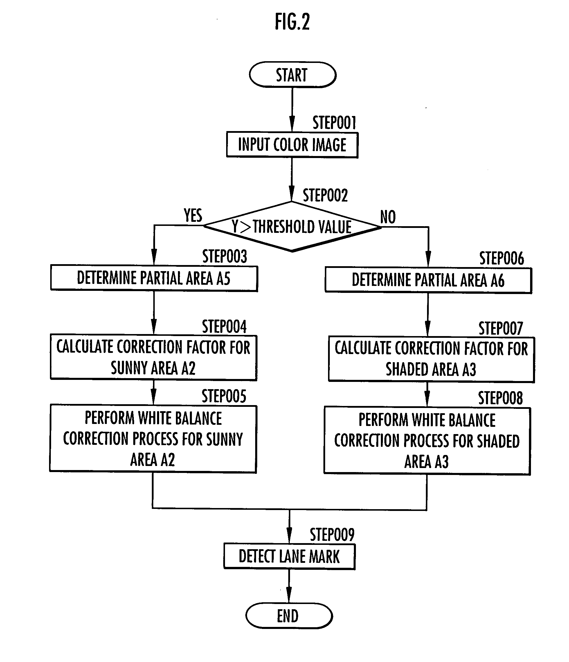
[0053]According to the above, the white balance processing means 5 uses the sum values Rsum′, Gsum′, Bsum′, and Ysum′ of the R value, G value, B value, and luminance value Y of each pixel data calculated for the sunny area A2 and the shaded area A3, instead of using the sum values Rsum, Gsum, Bsum, and Ysum of the R value, G value, B value, and luminance value Y of each pixel data calculated for the partial area A5 and the partial area A6, when calculating the correction factors WR, WG, and WB (steps 004 and 007 in FIG. 2 of the first embodiment). Note that the sum values Rsum′, Gsum′, Bsum′, and Ysum′ indicate the general levels of the R value, G value, B value, and luminance value Y, respectively, in the sunny area A2 and the shaded area A3.

[0054]Also in this case, the bias in the level between the color components in each of the sunny area A2 and the shaded area A3 is reduced by the white balance process in the above steps 005 and 008, which thereby corrects the difference in the...

second embodiment

[0059]Furthermore, in the second embodiment, the white balance processing means 5 can use mean values Rmed′, Gmed′, Bmed′, and Ymed′ in the sunny area A2 and the shaded area A3, instead of using the sum values Rsum′, Gsum′, Bsum′, and Ysum′ in the sunny area A2 and the shaded area A3, when calculating the correction factors WR, WG, and WB. In this instance, the mean values Rmed′, Gmed′, Bmed′, and Ymed′ also indicate the general levels of the R, G, and B values and the luminance value Y in the sunny area A2 and the shaded area A3, respectively. Therefore, the white balance processing means 5 can calculate the correction factors WR, WG, and WB so as to reduce the degree of divergence in the level between the R, G, and B values in the sunny area A2 and the shaded area A3, similarly to the case of using the sum values Rsum′, Gsum′, Bsum′, and Ysum′.

[0060]Moreover, in the first and second embodiments, the road sign recognition device can include an external sensor such as a spectrometer...


PUM


Abstract

The present invention includes: image capturing means (2) which captures a color image of a road via imaging means (7); area extraction means (6) which extracts areas having a similar color feature value from the captured color image of the road; white balance processing means (5) which performs, for each of the extracted areas, a white balance process of correcting each pixel data in the extracted area so as to reduce the degree of divergence in the level between color components according to a level balance between the color components of the pixel data in the extracted area; and road sign detection means (6) which detects a road sign on the road from the color image subjected to the white balance process. Thus, even if the road illumination state is partially different, it is possible to accurately detect a road sign such as a lane mark from the captured color image of the road via the imaging means such as a camera.

Description

TECHNICAL FIELD[0001]The present invention relates to a vehicle and road sign recognition device for detecting a road sign such as a lane mark on a road by processing an image of the road captured via imaging means such as a camera.BACKGROUND ART[0002]In recent years, there has been suggested a technology for detecting a lane mark such as a white line on a road such as an express highway by capturing an image of the road along which a vehicle travels with imaging means such as a CCD camera mounted on the vehicle and processing the captured image (for example, refer to Japanese Patent Laid-Open No. Hei 11(1999)-85999 (hereinafter, referred to as Patent Document 1)).[0003]The white line detection device for a vehicle in Patent Document 1 extracts an edge point (negative edge point) where binary data changes from light (white) to dark (black) over the entire image area and an edge point (positive edge point) where binary data changes from dark (black) to light (white) by using a monoch...

Claims


Application Information

Patent Timeline
IPC IPC(8): G06K9/00G06V10/56
CPCG06K9/00798G06K9/4652G06V20/588G06V10/56
Inventor NAKAMORI, TAKUMAKOBAYASHI, SACHIOAOKI, TOMOYOSHIMORI, NAOKI
Owner HONDA MOTOR CO LTD
Why Eureka
Try Eureka