Fiber optic sensing device and method

a fiber optic and sensing device technology, applied in the direction of optical radiation measurement, instruments, machines/engines, etc., can solve the problems of slow starting or loading of steam turbines, damage to steam turbines, and failure to monitor temperature at all points where condensation can occur or water

Inactive Publication Date: 2010-03-25
GENERAL ELECTRIC CO
View PDF10 Cites 38 Cited by
  • Summary
  • Abstract
  • Description
  • Claims
  • Application Information

AI Technical Summary

Problems solved by technology

This condensation can slow starting or loading of the steam turbine.
If the condensation is not detected, it can damage the steam turbine during start-up, loading or operating conditions of the turbine.
It is difficult, however, to monitor temperature at all points where condensation can occur or water can collect due to the configuration of the various steam or condensate pipes, valves, and steam entry and exit points in the plant.
Additionally, the steam turbine casing has a temperature gradient and expands differently at different portions due to transient operation and its complex geometry.
One limitation of the thermocouples is that thermocouples are single point measurements and can be easily misplaced in a region close to an intended target area resulting in a vastly different temperature reading due to the complex geometry of the turbine casing and internal heating conditions.
It is difficult and expensive to provide large number of thermocouples in a distributed manner around the turbine.

Method used


Image

  • Fiber optic sensing device and method
  • Fiber optic sensing device and method
  • Fiber optic sensing device and method

Examples


Embodiment Construction

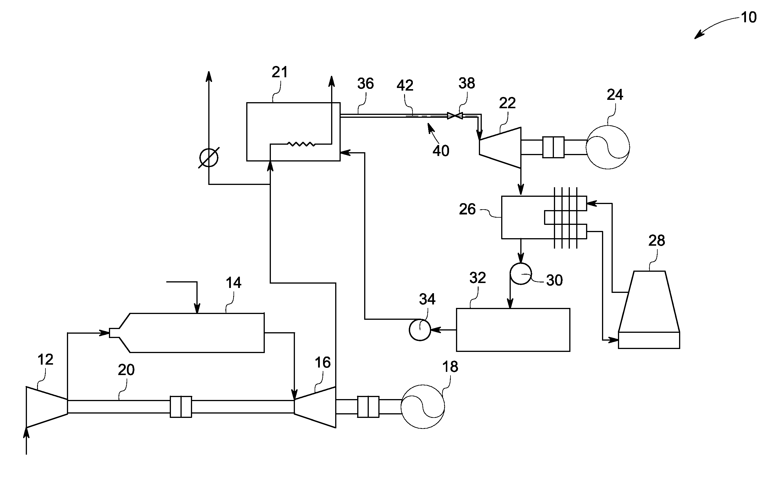
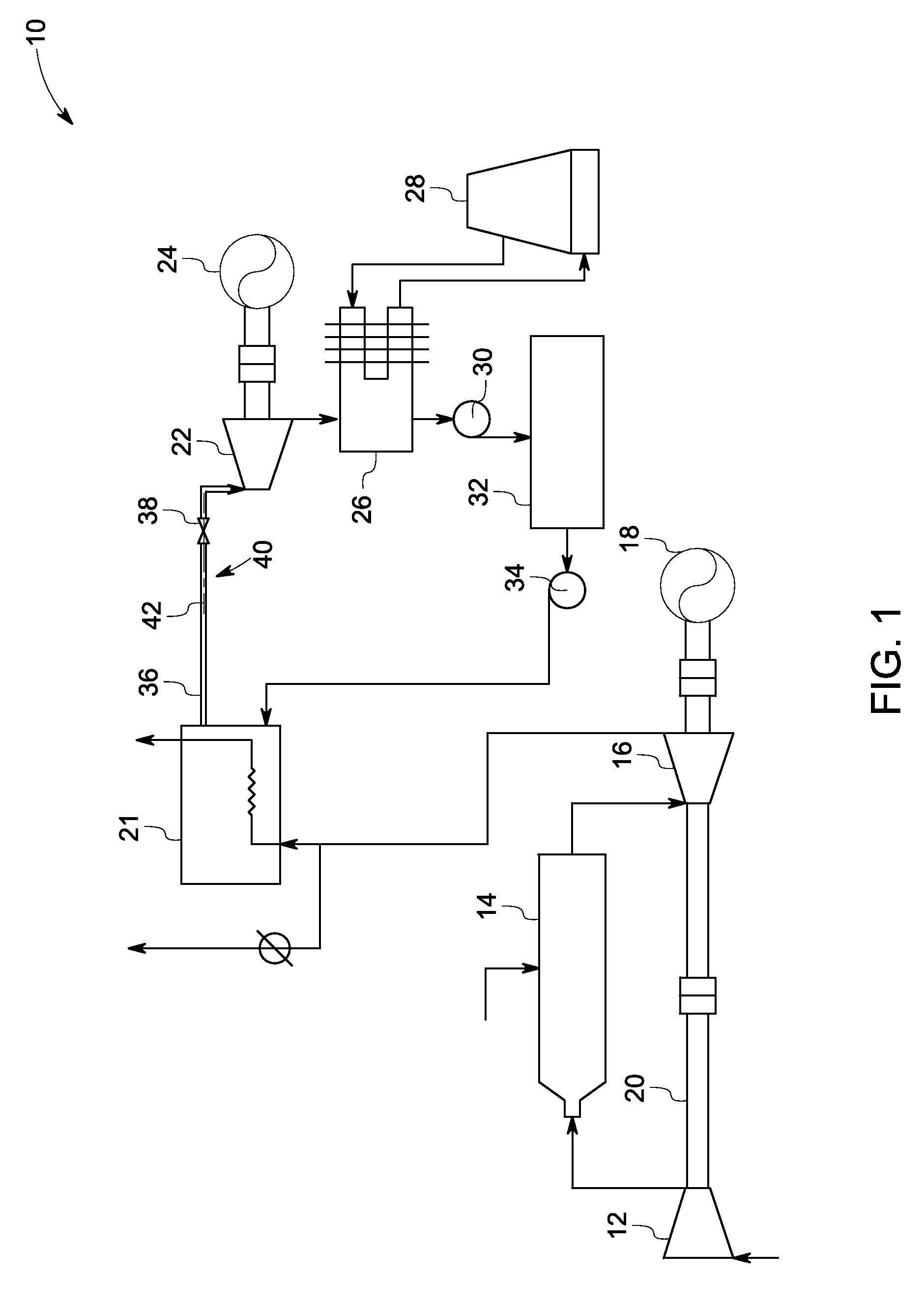
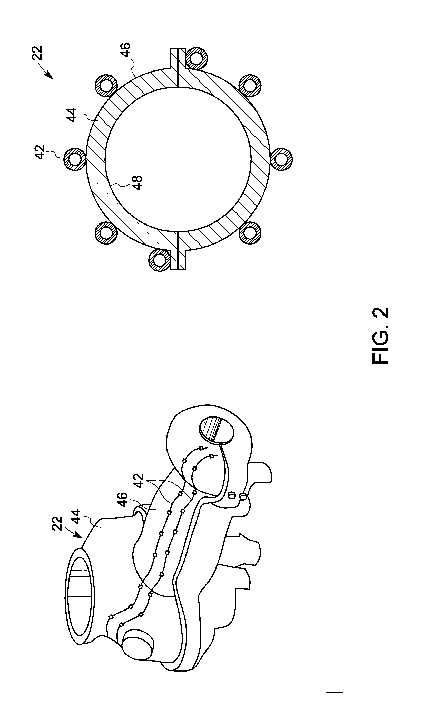
[0016]As discussed in detail below, embodiments of the present invention comprise a device including a stationary component and a rotary component. A fiber optic sensing system includes at least one cable having one or more fiber optic sensors disposed on the stationary component, the rotary component, or a combination thereof. The fiber optic sensing system is configured to detect one or more first parameters including temperature, strain, pressure, vibration, torque, or combinations thereof related to the stationary component, rotary component, or combinations thereof. In one embodiment, the device includes a rotary machine such as a steam turbine. The sensing cables are disposed in a distributed manner along an inner and / or outer surface of the stationary component, or rotary component.

[0017]The detected first parameters are used to determine thermal expansion, condensation, or the like related to the components. Embodiments of the present invention provide a real time and accura...


PUM


Abstract

A device includes a stationary, rotary component, and a fiber optic sensing system. The fiber optic sensing system includes a cable having one or more fiber optic sensors disposed on the stationary component, the rotary component, or combinations thereof. The fiber optic sensing system is configured to detect one or more first parameters including temperature, strain, pressure, vibration, torque; or combinations thereof related to the stationary component, the rotary component, or combinations thereof. The one or more first parameters is used to determine one or more second parameters including thermal expansion, clearance, fluid flow rate variation, condensation, fluid leakage, thermal loss, life, thermal stress, or combinations thereof related to the stationary component, the rotary component, or combinations thereof.

Description

BACKGROUND[0001]The invention relates generally to fiber optic sensing devices, and more particularly, to a fiber optic sensing system and method for detecting multiple parameters from a power generation system or a component, for example, a turbomachine such as a steam turbine, or the like.[0002]Turbomachines such as a steam turbine plant may include several steam or condensate pipes leading to and from a steam turbine and accessories of the plant. The steam or condensate pipes may also be provided with several valves. Steam condensation may occur at various points in the pipes, valves, and steam turbine. This condensation can slow starting or loading of the steam turbine. If the condensation is not detected, it can damage the steam turbine during start-up, loading or operating conditions of the turbine. Monitoring temperature at the various points of the steam turbine plant more continuously (rather than discretely) can help to identify the water or moisture traps and improve stea...

Claims


Application Information

Patent Timeline
Patent Type & Authority Applications(United States)
IPC IPC(8): G02B6/00
CPCF01D17/02G01D5/3537G02B6/02195F01D21/003
Inventor ZHENG, DANIANTURNQUIST, NORMAN ARNOLDEISENZOPF, PETER JOHNMCCARTHY, KEVIN THOMASXIA, HUASWINTEK, ROY PAUL
Owner GENERAL ELECTRIC CO
Why Eureka
Try Eureka