Swim fins

a technology of swim fins and fins, applied in the field of swim fins, can solve the problems of severe ankle strain and calf muscle fatigue, human feet providing relatively poor thrust, and typical swim fins having several problems

Inactive Publication Date: 2010-03-25
JOHNSON MARK R
View PDF25 Cites 18 Cited by
  • Summary
  • Abstract
  • Description
  • Claims
  • Application Information

AI Technical Summary

Benefits of technology

[0008]A need therefore exists for a swim fin that e...

Problems solved by technology

For example, scuba divers use swim fins to move through water efficiently, as human feet provide relatively poor thrust, especially when the diver is carrying equipment that increases hydrodynamic drag.
Unfortunately, typical swim fins have several problems.
For example, since typical swim fins attach only to the foot and heel of a swimmer, typical swim fins can cause severe ankle strain and calf muscle fatigue.
Further, the ankle does not generally orient the foot optimally for forward thrust, thus reducing the efficiency of the hydrofoil properties of the fin.
Further, typical swim fins increase the footprint of the swimmer and are constructed of heavy and bulky materials, thus making it difficult to walk, as is often necessary when enter...

Method used


Image

  • Swim fins
  • Swim fins
  • Swim fins

Examples


first example swim

Fin

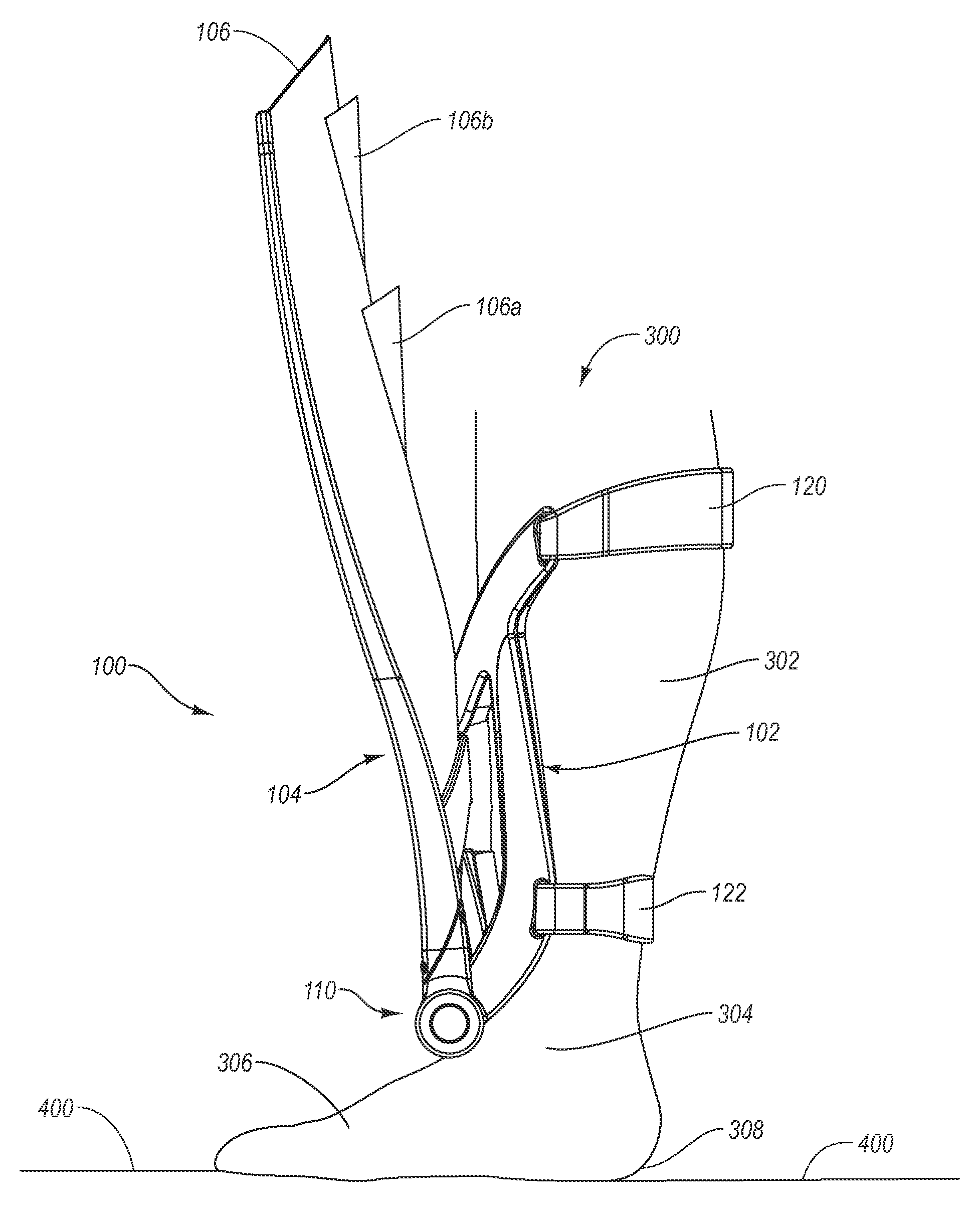
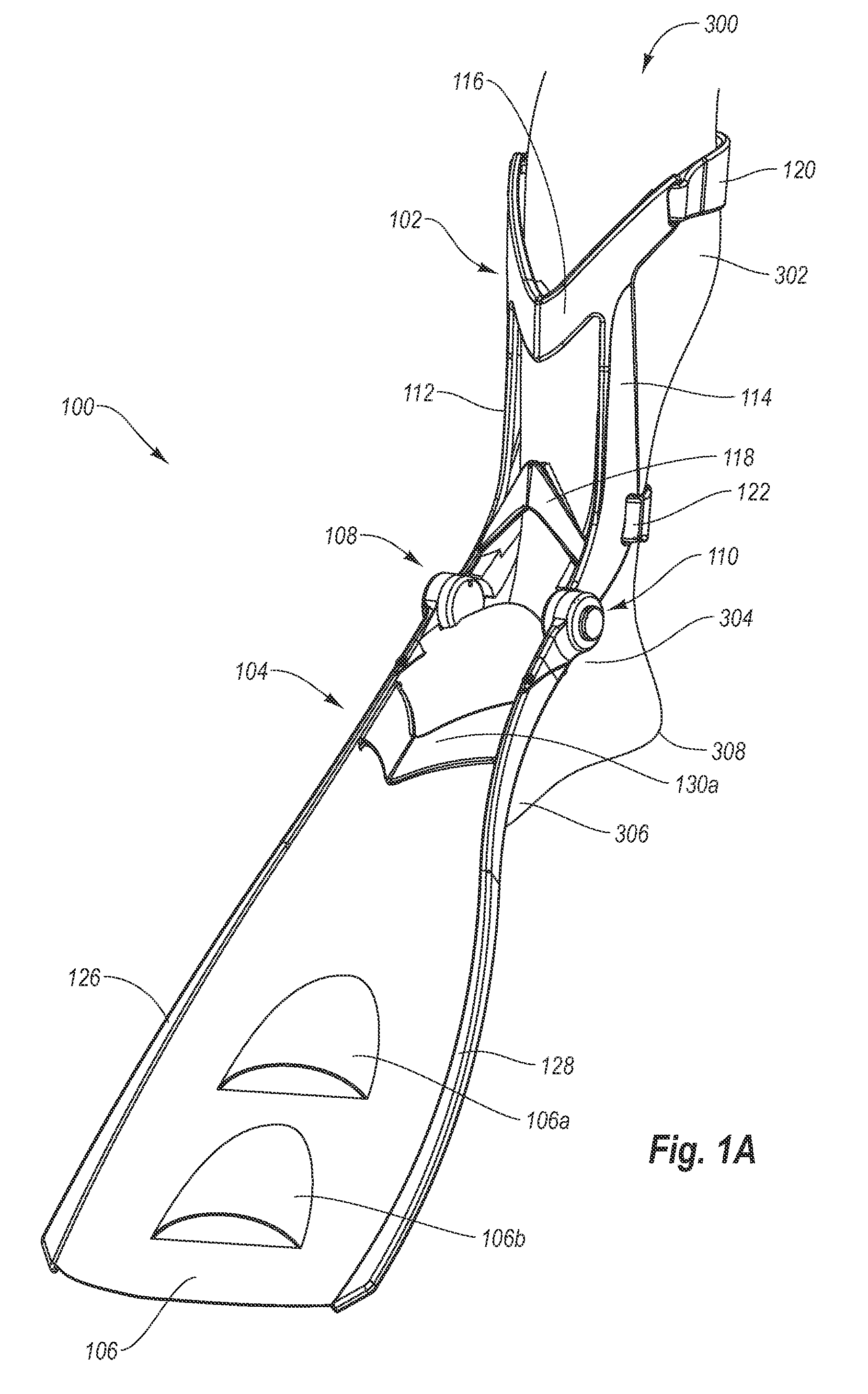
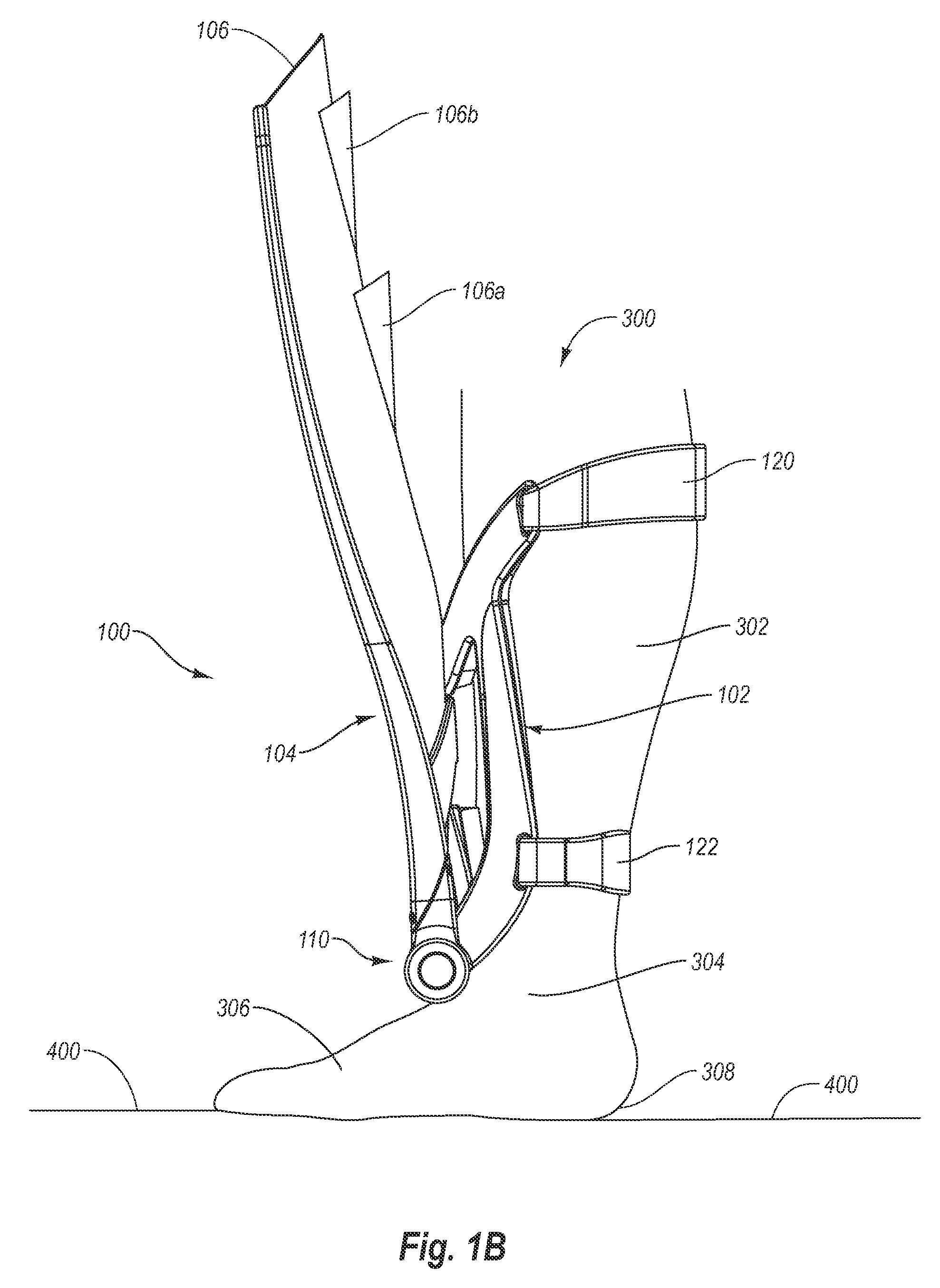
[0038]As disclosed in FIGS. 1A, 1B, and 1C, a first example swim fin 100 generally includes an upper support frame 102, a lower support frame 104, a lower blade 106 attached to the lower support frame 104, and a pair of hinge assemblies 108 and 110 connecting the upper support frame 102 and the lower support frame 104. The hinge assemblies 108 and 110 connect the upper support frame 102 to the lower support frame 104 and allow the lower support frame 104 to be rotated upward from a “swimming position,” disclosed in FIG. 1A, to a “walking position,” disclosed in FIG. 1B, while the upper support frame 102 remains securely attached to the lower leg 302 of a swimmer 300. The swimming position disclosed in FIG. 1A enables the swimmer 300 to swim through water with increased thrust as compared to swimming with a bare foot. The walking position disclosed in FIG. 1B enables the swimmer 300 to walk on a surface 400 without the swim fin substantially contacting the surface 400 and without ...

second example swim

Fin

[0049]With reference now to FIGS. 2A, 2B, and 2C, a second example swim fin 100′ is disclosed. The swim fin 100′ is identical to the swim fin 100, with the exception of the lower support frame 104′, the blade 106′, the hinge assemblies 108′ and 110′ and a latch 132.

[0050]As disclosed in FIGS. 2A, 2B, and 2C, the lower support frame 104′ includes an additional cross member 130b that augments the supporting function of the cross member 130a by supporting the braces 126′ and the 128′. Further, the blade 106′ incorporates hydrofoil chutes 106c, 106d, and 106e that allow water to be pushed through the blade 106′ in a direction that is generally inline with the forward motion of the swimmer 300. Like the chutes 106a and 106b, the chutes 106c, 106d, and 106e may be formed from a material that allows the chutes to transition from protruding from the top surface of the blade 106 (during a down stroke) to protruding from the bottom surface of the blade 106 (during an up stroke) in order to...


PUM


Abstract

Swim fins that attach to the legs of a swimmer to aid movement through the water. In one example embodiment, a swim fin includes an upper support frame, a lower support frame, a lower blade attached to the lower support frame, and at least one hinge assembly connecting the upper support frame to the lower support frame. The upper support is configured to be generally positioned along and attached to the front of a swimmer's lower leg between the swimmer's knee and ankle The lower support frame is configured to extend, in a swimming position, from a position proximate the swimmer's ankle to a position beyond the end of the swimmer's foot. The at least one hinge assembly allows the lower support frame to be rotated upward from the swimming position to a walking position. The walking position enables the swimmer to walk barefoot on a surface without the lower support frame nor the lower blade substantially contacting the surface.

Description

CROSS REFERENCE TO A RELATED APPLICATION[0001]This application claims priority to and the benefit of U.S. Provisional Patent Application Ser. No. 61 / 100,207, entitled SWIM FINS, which was filed on Sep. 25, 2008, and is hereby incorporated by reference in its entirety.BACKGROUND[0002]1. Field of Invention[0003]The present invention generally relates swim fins and, in particular, to swim fins that attach to the legs of a swimmer to aid movement through the water.[0004]2. Description of Related Art[0005]Typical swim fins are worn on the foot of a swimmer to aid movement through the water while surface swimming or participating in swimming-related activities such as bodyboarding, bodysurfing, kneeboarding, riverboarding, snorkeling, and various types of underwater diving. For example, scuba divers use swim fins to move through water efficiently, as human feet provide relatively poor thrust, especially when the diver is carrying equipment that increases hydrodynamic drag.[0006]Unfortunat...

Claims


Application Information

Patent Timeline
IPC IPC(8): A63B31/08A63B31/12
CPCA63B2031/112A63B31/11A63B31/12
Inventor JOHNSON, MARK R.
Owner JOHNSON MARK R
Why Eureka
Try Eureka