Hollow tissue inosculation apparatus

a tissue inosculation and hollow technology, applied in the field of hollow tissue inosculation apparatus, can solve the problems of heavy load applied to the blood vessel when the staples penetrate through the blood vessel, and achieve the effect of reducing the amount of staples in the blood vessel

Inactive Publication Date: 2010-03-25
OLYMPUS CORP
View PDF23 Cites 9 Cited by
  • Summary
  • Abstract
  • Description
  • Claims
  • Application Information

AI Technical Summary

Benefits of technology

[0007]The present invention is directed to a hollow tissue inosculation apparatus to inosculate two hollow tissues to each other with a staple having a plurality of elastically deformable bent staple pins. The hollow tissue inosculation apparatus includes a staple holder to hold the staple, a curvature control mechanism to control curvature of the staple pins of the staple held in the staple holder, and a gap control mechanism to control gaps between the staple holder and the hollow tissues. The curvature control mechanism substantially straightens the staple pins. The gap control mechanism reduces the gaps to cause the substantially s

Problems solved by technology

Thus, a load applied to the blood vessel when the s

Method used


Image

  • Hollow tissue inosculation apparatus
  • Hollow tissue inosculation apparatus
  • Hollow tissue inosculation apparatus

Examples


first embodiment

[0075]The present embodiment concerns a staple and a hollow tissue inosculation apparatus to inosculate two hollow tissues to each other. The hollow tissues are specifically blood vessels.

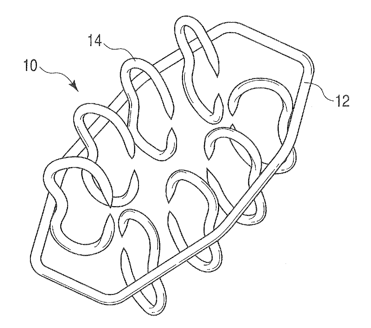
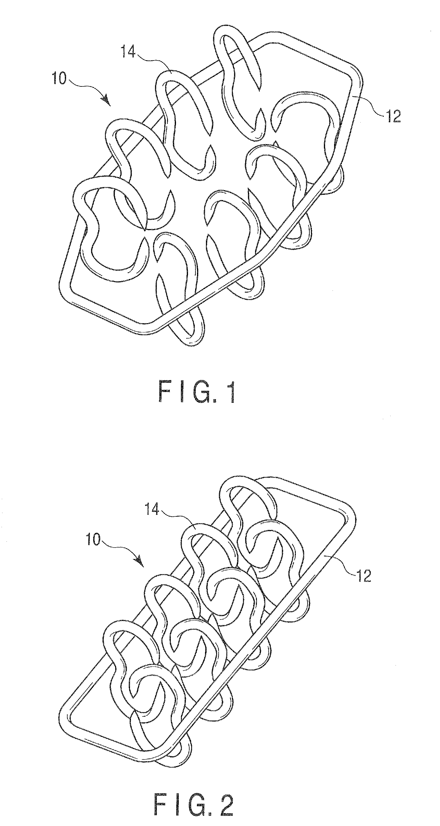
[0076]The staple as a fastening to inosculate two hollow tissues will be first described with reference to FIGS. 1 and 2. Each of FIGS. 1 and 2 is a perspective view of the staple according to the present embodiment. FIG. 1 shows the staple in a natural state, and FIG. 2 shows the staple attached to the hollow tissue inosculation apparatus.

[0077]As shown in FIGS. 1 and 2, the staple 10 has an elastically deformable generally ring-like ring member 12 and a plurality of elastically deformable bent staple pins 14. Each staple pin 14 is fixed on the inner side of the ring member 12. An axis of the ring member 12 is on a plane, an axis of each staple pin 14 is on a different plane, and these planes are generally perpendicular to each other. Here, an axis of a member means a line extending along this mem...

second embodiment

[0174]The present embodiment is different from the first embodiment in disposing positions of coronary-artery supports 312 and graft supports 412 with respect to a fixing portion 314 and a fixing portion 414, but any other structures are basically the same.

[0175]In the present embodiment, as shown in FIG. 53, for example, contact positions of the coronary-artery supports 312 and the graft supports 412 with the coronary artery 50 and the graft 60 are positioned on an outer side of positions that the staple pins 14 of the staple 10 penetrate through the coronary artery 50 and the graft 60.

[0176]An operation of inosculating the coronary artery with the graft with the staple 10 by using a hollow tissue inosculation apparatus according to the present embodiment will now be described hereinafter with reference to FIGS. 55 to 65.

[0177]First, like the first embodiment, the staple 10 is attached to a staple holder 200. Then, outer pillars 512, inner pillars 532, outer pillars 612, and inner ...

third embodiment

[0187]In the first and second embodiments, the coronary-artery supports 312 and the graft supports 412 each has cylindrical shape, whereas the third embodiment is directed to alternative coronary-artery and graft supports having another shape. Since the coronary-artery supports and graft supports may have generally the same shape, the graft supports will be here representatively described with reference to FIG. 64.

[0188]As shown in FIG. 64, each graft support 452 according to the third embodiment comprises a linear portion 454 extending linearly, and a plurality of projections 456 inwardly projecting from the linear portion 454. The linear portion 454 is outwardly positioned with respect to the line along which the pins 14 of the staple 10 penetrate through the graft 60. The projections 456 are provided on the linear portion 454 at regular intervals so that the pins 14 of the staple 10 have penetrated through the graft 60 pass through the spaces between the projections. The linear p...


PUM


Abstract

A hollow tissue inosculation apparatus inosculate two hollow tissues with a staple having elastically deformable pins. The inosculation apparatus includes a holder to hold the staple, a curvature control mechanism to control curvature of the pins of the staple held in the holder so as to straighten the pins, and a gap control mechanism to control gaps between the holder and the hollow tissues so as to reduce the gaps to cause the straightened pins to penetrate through the hollow tissues. The gap control mechanism includes two support mechanisms to support the hollow tissues and a mechanism to move the support mechanisms with respect to the holder. The support mechanisms include supports to support the hollow tissues when the pins are stuck into the hollow tissues. Contact parts of the supports with the hollow tissues are spaced apart from positions where the pins penetrate through the hollow tissue.

Description

CROSS-REFERENCE TO RELATED APPLICATIONS[0001]This application is based upon and claims the benefit of priority from prior Japanese Patent Application No. 2008-240556, filed Sep. 19, 2008, the entire contents of which are incorporated herein by reference.BACKGROUND OF THE INVENTION[0002]1. Field of the Invention[0003]The present invention relates to a hollow tissue inosculation apparatus to inosculate two hollow tissues to each other.[0004]2. Description of the Related Art[0005]Hollow tissue inosculation apparatus include an anastomotic apparatus to anastomose blood vessels as hollow tissues in coronary-artery bypass surgery, for example. U.S. Pat. No. 7,300,444, for example, discloses an inosculation apparatus that uses U-shaped staples each having a pair of sharpened tips. In this apparatus, when inosculating two blood vessels, a member for ejecting the staples and a bending table for deforming the staples are located inside and outside the blood vessels and the staples are stuck t...

Claims


Application Information

Patent Timeline
IPC IPC(8): A61B17/08A61B17/068
CPCA61B17/11A61B17/115A61B2017/1139A61B2017/0641A61B2017/1107A61B17/320016
Inventor YASUDA, MAMORU
Owner OLYMPUS CORP
Why Eureka
Try Eureka