Travel route generating method for unmanned vehicle

a technology for generating routes and unmanned vehicles, applied in the direction of process and machine control, distance measurement, instruments, etc., can solve the problems of reducing the work efficiency as a whole, the route generating method based on the drawings described above suffers from the same problems, and the minimum vehicle constraint conditions cannot be satisfied in some cases. , to achieve the effect of exceeding the turning capacity of the vehicle, reducing the period of time required, and minimizing the cost function valu

Active Publication Date: 2010-03-25
KOMATSU LTD +1
View PDF1 Cites 138 Cited by
  • Summary
  • Abstract
  • Description
  • Claims
  • Application Information

AI Technical Summary

Benefits of technology

[0069]a) The travel route 10 is generated so as to satisfy the vehicle constraint conditions and / or the geometrical constraint conditions, whereby the unmanned vehicle 20 is allowed to travel safely without interfering with an obstacle 9 or the like, and without exceeding the turning capacity of the vehicle.
[0070]b) The travel route 10 is generated so as to minimize the cost function value, whereby the unmanned vehicle 20 traveling along this travel route 10 is allowed to travel with lower load on its tires and vehicle body, with a reduced period of time required for the travel, and with lower fuel consumption. This minimizes the costs required for operating the unmanned vehicle 20.
[0071]The second and third aspects of the invention provide advantageous effects as follows.
[0072]c) A switchback point 12 is determined such that the cost function value is minimized, whereby the unmanned vehicle 20 traveling along the travel route 10 including this switchback point 12 is allowed to travel with lower load on its tires and vehicle body, with reduced time required for the travel, and with lower fuel consumption. This minimizes the costs required for operating the unmanned vehicle 20.
[0073]The fourth aspect of the invention is an invention specifying the travel route generating step of the first aspect of the invention.
[0074]The fifth aspect of the invention is an invention specifying the interpolation step of the fourth aspect of the invention.

Problems solved by technology

Thus, this method requires a lot of time and labor for generating a travel route, impairing the work efficiency as a whole.
The route generating method based on drawings described above also suffers from the same problems.
However, these techniques pose various problems when taking into consideration the controllability of the unmanned vehicles and the productivity.
If these conventionally techniques are directly applied to an unmanned vehicle driving system, even minimum vehicle constraint conditions cannot be satisfied in some cases.
Therefore, there will be a chance that an unmanned vehicle cannot turn around in a travel route generated by this method, making it impossible to run the vehicle.
According to another conventional technique using random search, the algorithm depends on random numbers, which makes it difficult to find the cause of trouble when travel route generation becomes impossible.
Furthermore, travel routes generated by these conventional techniques are not necessarily optimal routes in terms of cost.
In particular, dump truck tires are so expensive that it is imperative to reduce the load on the tires.
Therefore, it becomes an important issue how to generate a travel route minimizing the costs caused by travel of unmanned vehicles.
None of the conventional techniques generates an optimal travel route taking into consideration the costs caused by travel of a vehicle as described above.
Therefore, the work efficiency is poor and the productivity is low.
This will also pose a problem of reduced productivity because reduction of vehicle speed or forcible steering operation may be obliged at the joint between the curves.
This poses a problem in terms of versatility.
Specifically, since the switchback points are set uniformly in a fixed pattern, the travel route containing such switchback points is not optimal one that enables reduction the traveling cost.

Method used


Image

  • Travel route generating method for unmanned vehicle
  • Travel route generating method for unmanned vehicle
  • Travel route generating method for unmanned vehicle

Examples


example 1

Route Generation Example 1

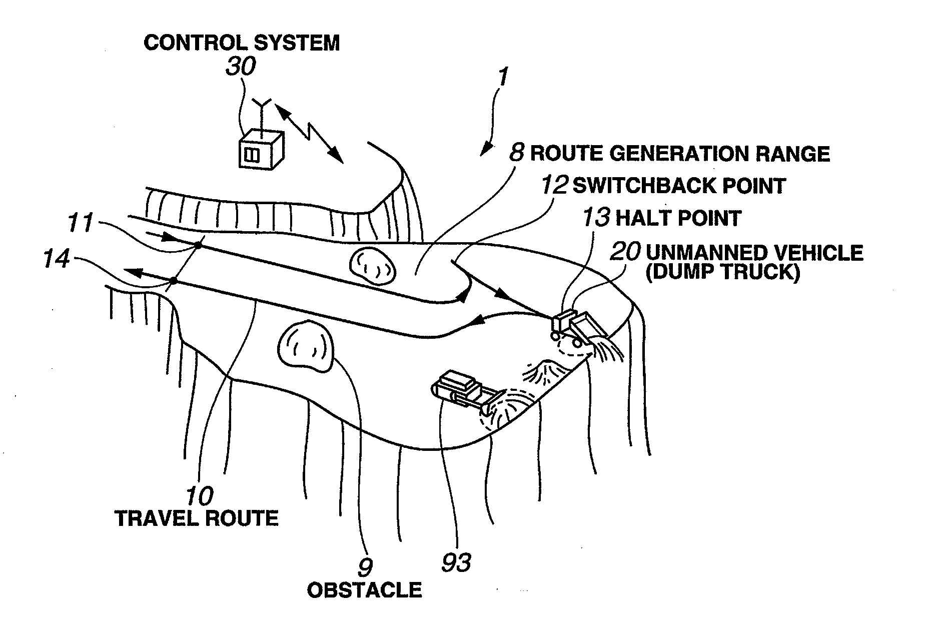
[0437]FIG. 33A shows geometrical conditions given in the route generation example 1. In FIG. 33A, the reference numeral 8a denotes the outline of a route generation range 8, 9a denotes the outline of an obstacle 9. The directions at the entrance point 11, the exit point 14, and the halt point 13 are indicated by the arrows. The halt point 13 in the route generation example 1 is a place to discharge soil, and thus the unmanned vehicle 20 must reach the halt point 13 in its reverse traveling state.

[0438]FIG. 33B shows the outline 8b of the route generation range 8 and the outline 9b of the obstacle 9 as obtained by Minkowski-summing the outline 8a of the route generation range 8, the outline 9a of the obstacle 9 and the disc.

[0439]FIG. 33C shows distribution of curvature of the travel route 10 and limit values based on minimum turning radii by plotting along the horizontal axis the travel distances from the entrance point 11 as the origin. As shown in FIG. 33...

example 2

Route Generation Example 2

[0441]FIGS. 34A, 34B, 34C, and 34D are diagrams showing route generation example 2, corresponding to FIGS. 33A, 33B, 33C, and 33D of the route generation example 1 described above.

[0442]In the route generation example 2, the unmanned vehicle 20 reaches the halt point 13 in its reverse traveling state to be loaded there. It is normally desirable that the switchback point 12 is located close to the halt point 13 so that the reverse travel distance is short. However, in this route generation example 2, there is an obstacle 9 near the halt point 13. Under this condition, there is no switchback point 12 satisfying the vehicle constraint conditions. Since the SA (global search) algorithm is employed in this embodiment, an optimal switchback point 12 can be searched for as shown in FIG. 34B.

example 3

Route Generation Example 3

[0443]FIGS. 35A, 35B, 35C, and 35D are diagrams showing route generation example 3, corresponding to FIGS. 33A, 33B, 33C, and 33D showing the route generation example 1 described above.

[0444]In the route generation example 3, the unmanned vehicle 20 enters the halt point 13 in its reverse traveling state to discharge soil there. Although there are a large number of obstacles 9 in the route generation range 8 of the route generation example 3, optimal travel route 10 can be generated, avoiding these obstacles 9.


PUM


Abstract

A travel route generating method for an unmanned vehicle, which includes a condition input step of inputting a vehicle constraint condition including a vehicle width and a minimum turning radius of the unmanned vehicle, and a geometrical constraint condition including a travel route generation range in which the unmanned vehicle is to travel, an obstacle to avoid, and a position and a direction of an entrance point and an exit point; and a travel route generating step of generating a travel route such that the vehicle constraint condition and the geometrical constraint condition are satisfied, and such that a function value of a cost function having at least a magnitude of a curve and/or a rate of change in the curve as a cost element is minimized.

Description

BACKGROUND OF THE INVENTION[0001]1. Technical Field[0002]This invention relates to a travel route generating method for an unmanned vehicle and, in particular, to a method of generating a travel route capable of minimizing a traveling cost of the unmanned vehicle.[0003]2. Related Art[0004]Unmanned vehicle driving systems are introduced in wide-area working sites such as quarrying sites and mines so that unmanned vehicles, in place of manned vehicles such as manned off-road dump trucks, perform soil transportation works in order to avoid accidents due to worker fatigue, to achieve laborsaving, and to improve productivity by enabling extended working time.[0005]Outlines of unmanned vehicle driving systems will be described below.[0006]A working site includes various areas such as loading sites, dumping sites, filling stations, and parking lots. These areas are interconnected by well-prepared transportation roads called haul roads, and lead-in roads, called access roads, extending from...

Claims


Application Information

Patent Timeline
Patent Type & Authority Applications(United States)
IPC IPC(8): G05D1/00
CPCG05D1/0217G05D2201/021G05D2201/0202
Inventor MAEKAWA, TAKASHINODA, TETSUYATAMURA, SHIGEFUMIOZAKI, TOMONORI
Owner KOMATSU LTD
Why Eureka
Try Eureka