Vehicle front structure

a front structure and vehicle technology, applied in the direction of vehicle components, vehicular safety arrangments, bumpers, etc., can solve the problem of reducing the strength of the vehicle front part, and achieve the effect of preventing “bending deformation” and local stress concentration in the vehicle front par

Active Publication Date: 2010-04-01
SUZUKI MOTOR CORP
View PDF9 Cites 4 Cited by
  • Summary
  • Abstract
  • Description
  • Claims
  • Application Information

AI Technical Summary

Benefits of technology

[0008]Accordingly, an object of the present invention is to provide a vehicle front structure that is reinforced so as to prevent local stress concentration.
[0011]According to the vehicle front structure in accordance with the present invention, the effect described below can be achieved. In the vehicle front structure in accordance with the present invention including the pair of side members arranged along the vehicle front and rear direction in both the right and left side parts in the vehicle width direction of the engine compartment; the bumper member which is configured so that the bumper of the vehicle can be attached thereto, and which is arranged along the vehicle width direction so as to connect the front end parts of the pair of side members with each other; the first reinforcement attached to the central part in the vehicle width direction of the bumper member; and the second reinforcement attached to the vehicle inside part of the corner part defined by the side member and the bumper member, wherein the first reinforcement is arranged so as to cover the upper part and the lower part in the vehicle vertical direction of the bumper member; wherein the side end part in the vehicle width direction of the first reinforcement, which is arranged in the upper part and the lower part, is formed so as to extend to the outside in the vehicle width direction toward the rear of the vehicle; wherein the second reinforcement is formed into a triangular shape corresponding to the corner part, and has the side part tilting to the outside in the vehicle width direction toward the rear of vehicle so as to connect the side member and the bumper member with each other; and wherein the side end part of the first reinforcement and the side part of the second reinforcement are arranged on the same straight line. Therefore, a load applied to the central part of the bumper member flows to the side member along the side end part of the first reinforcement and the side part of the second reinforcement, which are arranged on the same straight line, and this load is distributed. Furthermore, on the straight line along the side end part of the first reinforcement and the side part of the second reinforcement on the rear of the side member, usually, attachment parts of an apron side member, an extension panel, a fender apron brace, and the like, which are provided on the outside in the vehicle width direction of the side member, are arranged. Therefore, the load can be distributed to these members, so that local stress concentration in the vehicle front part can be prevented, and thereby the occurrence of deformation affecting the strength of vehicle front part, such as “bending deformation”, can be reliably prevented.
[0012]In the vehicle front structure in accordance with the present invention, the first reinforcement is formed so as to make a clearance which extends over the entirety in the vehicle width direction regarding at least one of the front part and the rear part of the bumper member. By not adopting a structure that enhances in an unbalanced way only the strength of the first reinforcement, the load applied to the central part of the bumper member can be distributed to the first reinforcement and further to the bumper member. Therefore, such a load can be absorbed while being distributed along the side end part of the first reinforcement and the side part of the second reinforcement, and further being distributed in the central part of the bumper member. Furthermore, when the load applied to the central part of the bumper member is applied so that the magnitude thereof is different in the vehicle vertical direction of the bumper member, and is applied so that a twisting force is generated in the bumper member, the load can be distributed to the upper part and the lower part of the first reinforcement without the twisting of the bumper together with the rotation of the entirety of the first reinforcement by the clearance extending over the entirety in the vehicle width direction of the first reinforcement. Therefore, the local stress concentration in the vehicle front part can be prevented further efficiently, and thereby the occurrence of deformation affecting the strength of vehicle front part, such as “bending deformation”, can be reliably prevented.

Problems solved by technology

The occurrence of “bending deformation” may cause a problem in that the strength of the vehicle front part is decreased.

Method used


Image

  • Vehicle front structure
  • Vehicle front structure
  • Vehicle front structure

Examples


Embodiment Construction

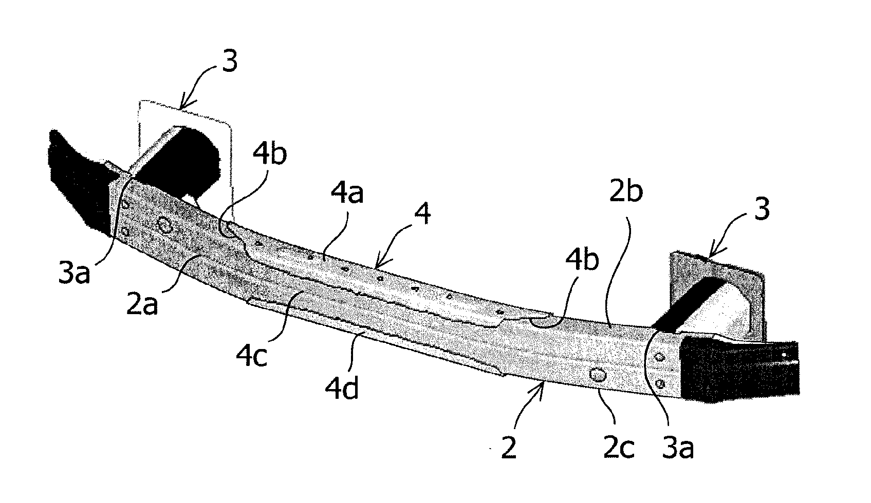
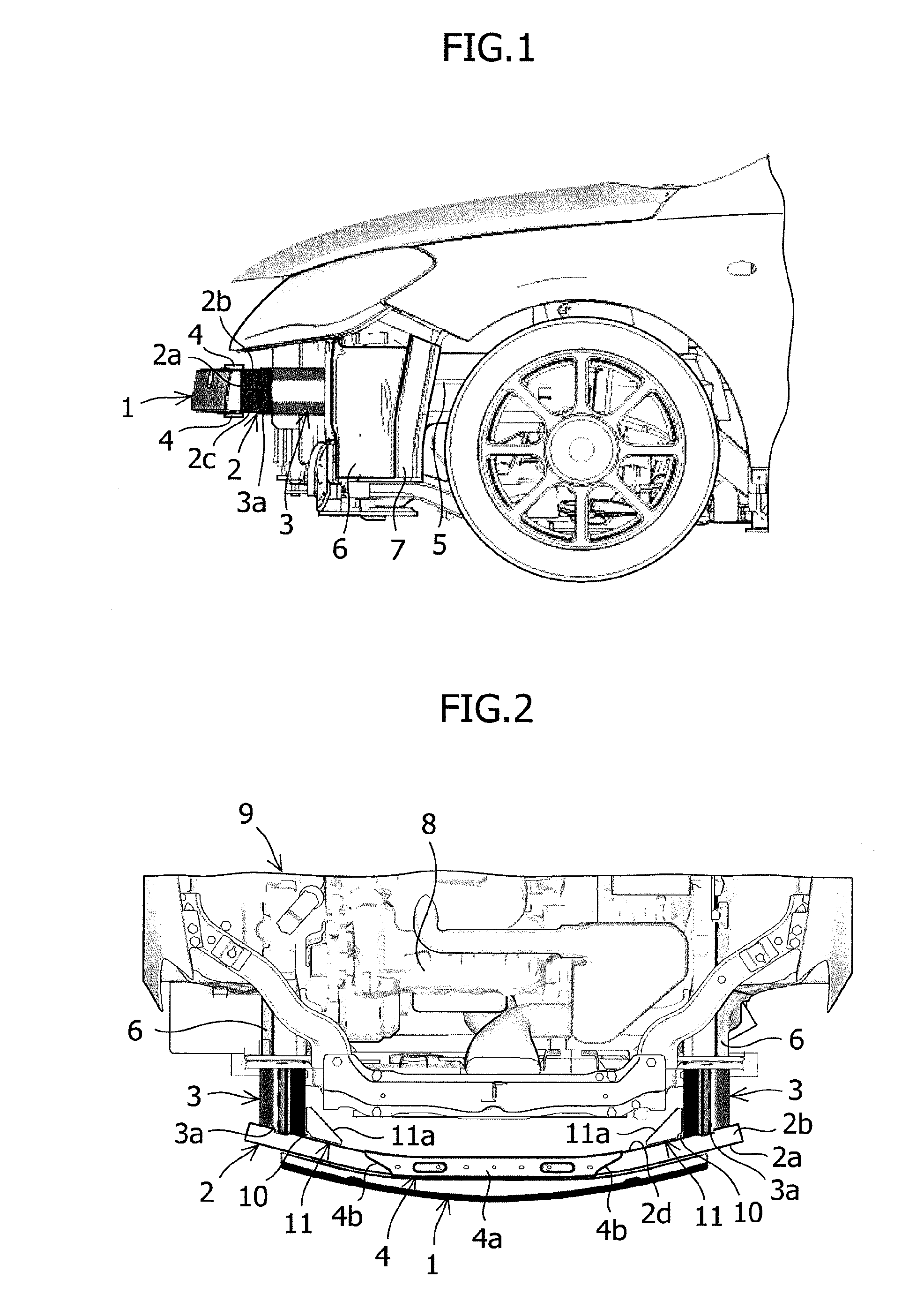
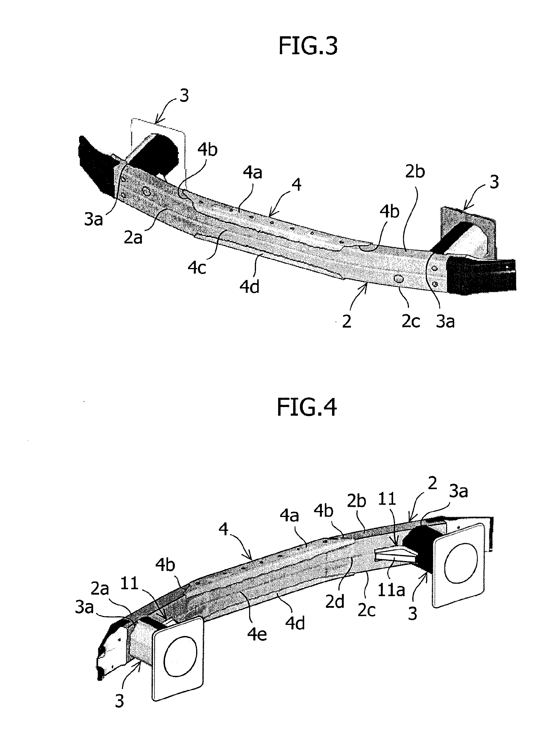
[0017]An embodiment of a vehicle front structure in accordance with the present invention will now be described with reference to the accompanying drawings. FIG. 1 is a side view schematically showing an internal structure around a bumper in a vehicle front part in this embodiment. In a lower portion of the vehicle front part, a bumper (absorber) 1 for buffering an impact and vibrations which are applied from the vehicle front is installed. This bumper 1 is attached to a front part 2a on the vehicle front of a bumper member 2, and further the bumper member 2 is attached to front end parts 3a on the vehicle front of side members 3. A first reinforcement 4 is installed so as to cover an upper part 2b and a lower part 2c in the vehicle vertical direction of the bumper member 2.

[0018]An apron side member 5 is attached to the rear of the side member 3, an extension panel 6 is attached to the outside in the vehicle width direction of the apron side member 5, and a fender apron brace 7 is ...


PUM


Abstract

A vehicle front structure reinforces a portion around a bumper to prevent local stress concentration. The vehicle front structure includes a first reinforcement (4) attached to the central part in the vehicle width direction of a bumper member (2), and includes second reinforcements (11) attached to the vehicle inside parts of corner parts (10) each defined by a side member (3) and the bumper member (2). The first reinforcement (4) is arranged so as to cover an upper part (2b) and a lower part (2c) of the bumper member (2). A side end part (4b) in the vehicle width direction of the first reinforcement (4), which is arranged in the upper part (2b) and the lower part (2c), is formed so as to extend to the outside in the vehicle width direction toward the rear of the vehicle. The second reinforcement (11) is formed into a triangular shape corresponding to the corner part (10), and has a side part (11a) tilting to the outside in the vehicle width direction toward the rear of vehicle so as to connect the side member (3) and the bumper member (2) with each other. The side end part (4d) of the first reinforcement (4) and the side part (11a) of the second reinforcement (11) are arranged on the same straight line.

Description

FIELD OF THE INVENTION[0001]The present invention relates to a vehicle front structure for reinforcing a portion around a bumper.BACKGROUND OF THE INVENTION[0002]A bumper provided in the front part of a vehicle is attached to a bumper member provided on a vehicle body, and this bumper member is attached to side members provided at both sides in the vehicle width direction of an engine compartment.[0003]When the vehicle receives a load such as an impact at the vehicle front, this load is mainly received by the bumper in the front part of the vehicle. At this time, a large stress is concentrated in the central part in the vehicle width direction of the bumper, and in an attachment part between the side member and the bumper member.[0004]Even if the impact applied to the bumper is small, the stress is concentrated especially in the central part in the vehicle width direction of the bumper member, and in an attachment part between the side member and the bumper member. At this time, at ...

Claims


Application Information

Patent Timeline
Patent Type & Authority Applications(United States)
IPC IPC(8): B60R19/26
CPCB60R19/023
Inventor HAMA, DAIGOROSUGIMOTO, SHOHEI
Owner SUZUKI MOTOR CORP
Why Eureka
Try Eureka