Slide door structure of vehicle

a technology for sliding doors and vehicles, applied in the direction of doors, roofs, wing accessories, etc., can solve the problems of sliding door stability deterioration, mechanism cannot stand the load properly, and the rollers would be derailed off the guide roller

Inactive Publication Date: 2010-04-01
MAZDA MOTOR CORP
View PDF4 Cites 23 Cited by
  • Summary
  • Abstract
  • Description
  • Claims
  • Application Information

AI Technical Summary

Benefits of technology

[0008]The present invention has been devised in view of the above-described problems, and an object of the present invention is to provide a slide door structure of a vehicle which can prevent the above-described expansion of guide-rail end in case the outward load acts on the slide door when the slide door is in the closed state.
[0009]According to the present invention, there is provided a slide door structure of a vehicle which has a slide door to slide in a vehicle longitudinal direction at a side of a vehicle body, comprising a guide rail extending in the vehicle longitudinal direction at the side of the vehicle body so as to guide a roller provided at the slide door, and an expansion preventing bracket provided at a front end portion of the guide rail so as to connect a pair of guide-face portions which face to each other for preventing an expansion of guide-rail end. Thereby, the expansion of guide-rail end at the front end portion of the guide rail can be prevented by the expansion preventing bracket. Accordingly, the enlargement of the gap between the side face of the vehicle body and the slide door which may be caused by the expansion of guide-rail end can be effectively prevented, thereby ensuring the stable support of the slide door.
[0010]According to an embodiment of the present invention, the roller and the side door are connected by a connecting bracket, and a first engagement portion is provided at the expansion preventing bracket and a second engagement portion is provided at the connecting bracket, the second engagement portion coming to engage with the first engagement portion in case a load which is a specified value or greater acts on the slide door outward in a vehicle width direction when the slide door is in a closed state. Thereby, the enlargement of the gap between the side face of the vehicle body and the slide door can be surely prevented.
[0011]According to another embodiment of the present invention, the guide rail is a center rail to support a middle portion of the slide door in a vehicle vertical direction for guiding the slide door in the vehicle longitudinal direction via the roller, and the center rail comprises the pair of guide-face portions which face to each other vertically and an opening of the guide-rail end which is formed between outside end portions of the pair of guide-face portions. Thus, the above-described advantages of the present invention can be effectively provided to the center rail which tends to have the problem of expansion of guide-rail end.
[0012]According to another embodiment of the present invention, the connecting bracket is equipped with a filler-lid stopper to prevent the slide door from sliding rearward beyond a specified distance when a filler lid is open, and the second engagement portion is provided at the filler-lid stopper. Thereby, the second engagement portion can be provided by using the existing member of the filler-lid stopper, not by using a new additional member, so that the structure can be simplified with low costs.

Problems solved by technology

This expansion of guide-rail end may cause an improper outward displacement of the roller, so that there is a concern that the rollers would be derailed off the guide roller in an extreme case.
Consequently, there is a problem in that the stable support of the slide door would deteriorate.
Consequently, the above-described mechanism could not stand the load properly, so that there is a problem in that the gap between the side face of the vehicle body and the slide door would become improperly large.

Method used


Image

  • Slide door structure of vehicle
  • Slide door structure of vehicle
  • Slide door structure of vehicle

Examples


Embodiment Construction

[0024]Hereinafter, a preferred embodiment of the present invention will be described referring to the accompanying drawings.

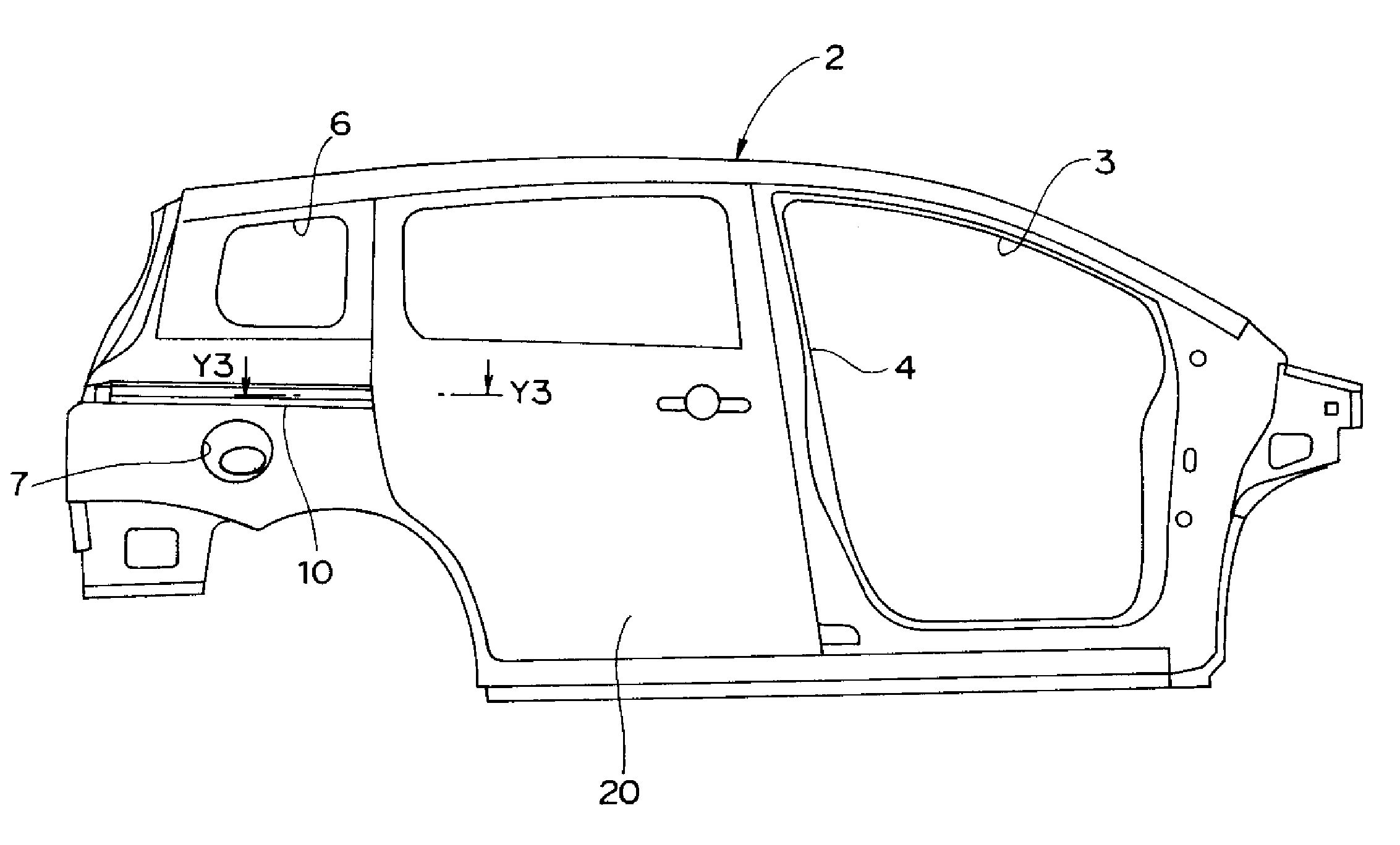
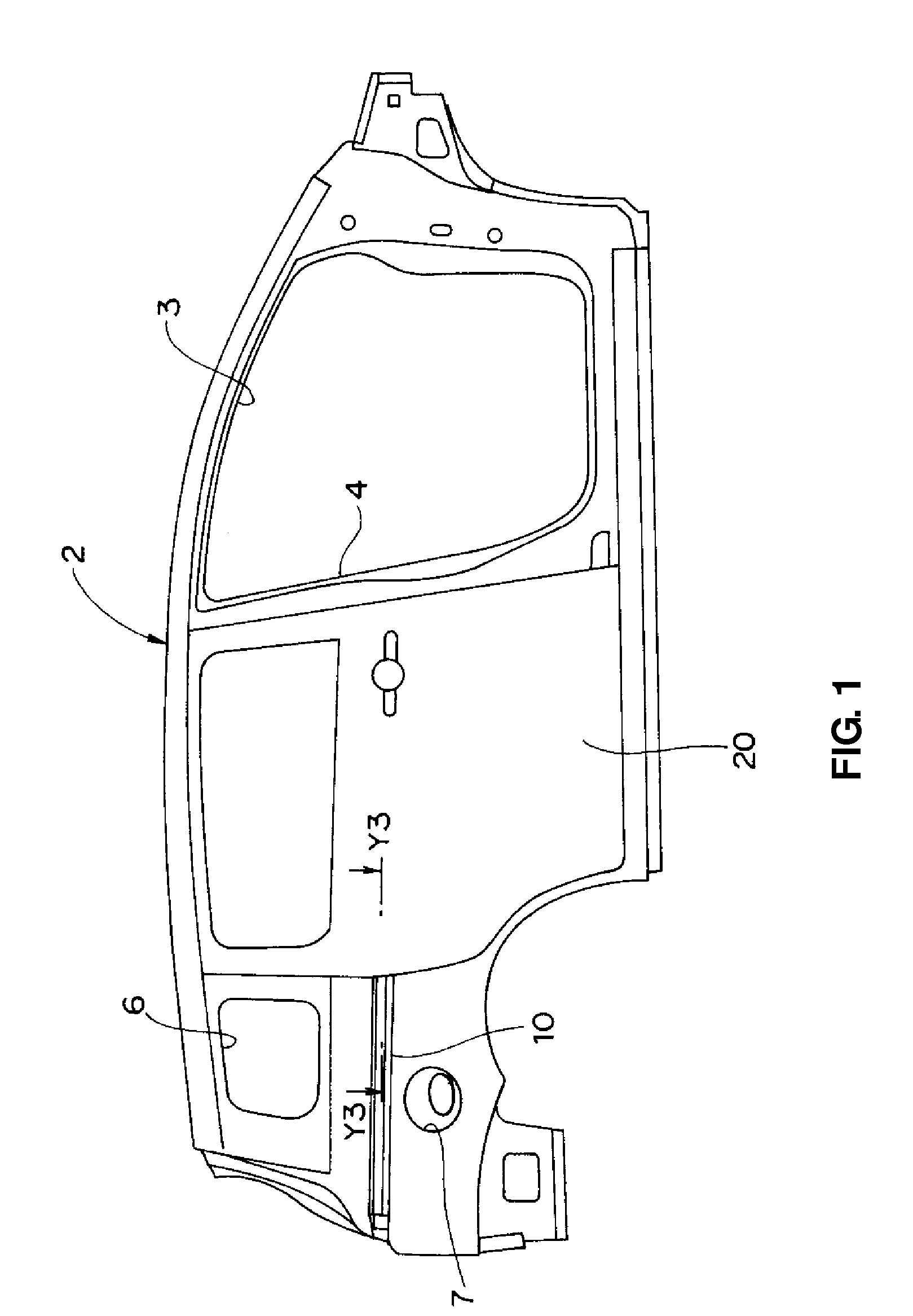
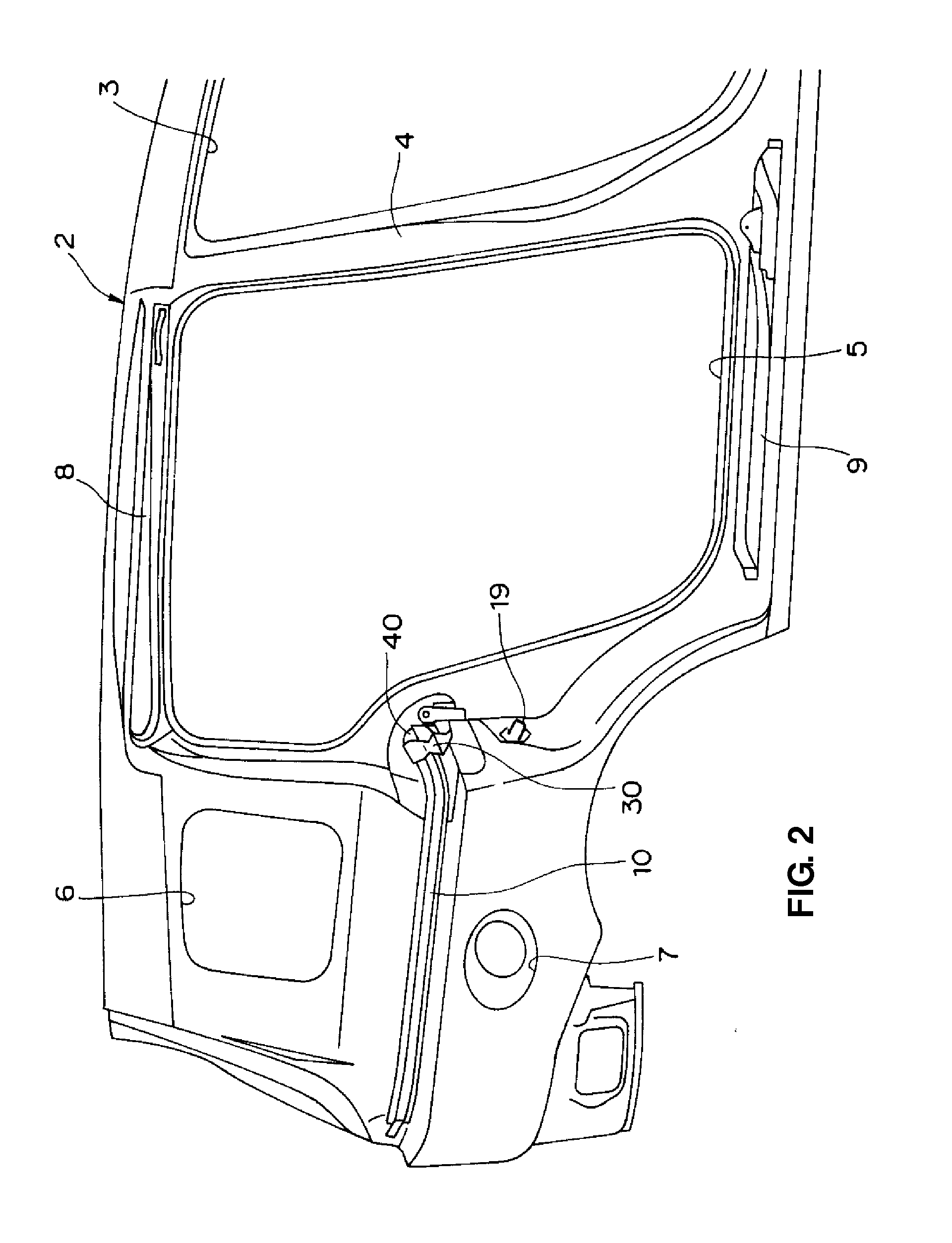
[0025]FIG. 1 is an explanatory side view of a right-side side panel of a vehicle body of an automotive vehicle with a slide door according to an embodiment of the present invention. FIG. 2 is a partial enlarged side view of a major portion of the right-side side panel of the vehicle body.

[0026]As shown in these figures, a slide door 20 of the automotive vehicle according to the present embodiment is provided at a side portion of a vehicle body so as to slide in a vehicle longitudinal direction for opening or closing a rear-side door opening 5. Herein, a front-side door opening 3 which is formed in front of a center pillar 4 is opened or closed by a normal hinge type of door (not illustrated).

[0027]Upper and lower guide rails 8, 9 are provided respectively at upper and lower edge portions of the rear-side door opening 5 of a side panel 2 of the vehicle body to g...


PUM


Abstract

There is provided a slide door structure of a vehicle which has a slide door to slide in a vehicle longitudinal direction at a side of a vehicle body, comprising a center rail which extends in the vehicle longitudinal direction at the side of the vehicle body so as to guide a roller provided at the slide door, and an expansion preventing bracket which is provided at a front end portion of the center rail so as to connect a pair of guide-face portions which face to each other for preventing an expansion of a center-rail end. Accordingly, the expansion of guide-rail end can be prevented in case the outward load acts on the slide door when the slide door is in the closed state.

Description

BACKGROUND OF THE INVENTION[0001]The present invention relates to a slide door structure of a vehicle which has a slide door to slide in a vehicle longitudinal direction at a side of a vehicle body.[0002]Conventionally, the slide door which slides in the vehicle longitudinal direction to open and close a door opening is well known as a side door provided at the side of the vehicle body (see Japanese Patent Laid-Open Publication No. 9-2065, for example). This slide door has been used well in so-called one-box type of vehicles.[0003]In such vehicles, a rail (guide rail) extending in the vehicle longitudinal direction is disposed at the side portion of the vehicle, and rollers to rotate and move along the guide rail are provided at the slide door. Thereby, the slide door slides in the vehicle longitudinal direction so as to open or close as the rollers rotate and move along the guide rail.[0004]In general, the guide rail comprises a pair of guide face portions which face to each other ...

Claims


Application Information

Patent Timeline
Patent Type & Authority Applications(United States)
IPC IPC(8): B60J5/06
CPCB60J5/06E05D15/1047E05Y2900/531E05Y2201/684E05Y2800/407E05D2015/1055E05D2015/1026E05D2015/1057
Inventor TAKAYA, HIROTAKAYOSHIDA, MOTOKIMONDEN, KATSUNORISHINODA, TAKAHIRO
Owner MAZDA MOTOR CORP
Why Eureka
Try Eureka