Wwan printed circuit antenna with three monopole antennas disposed on a same plane

Inactive Publication Date: 2010-04-01
ASUSTEK COMPUTER INC
View PDF5 Cites 30 Cited by
  • Summary
  • Abstract
  • Description
  • Claims
  • Application Information

AI Technical Summary

Problems solved by technology

However, to obtain better transmission efficiency, the structure changes of antennas usually refer to fine adjustments toward three-dimensional structures, and the manufacture is complicated

Method used


Image

  • Wwan printed circuit antenna with three monopole antennas disposed on a same plane
  • Wwan printed circuit antenna with three monopole antennas disposed on a same plane
  • Wwan printed circuit antenna with three monopole antennas disposed on a same plane

Examples


Embodiment Construction

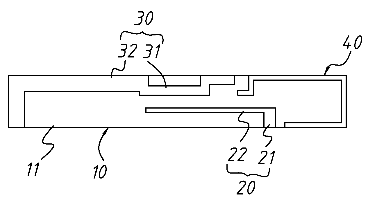
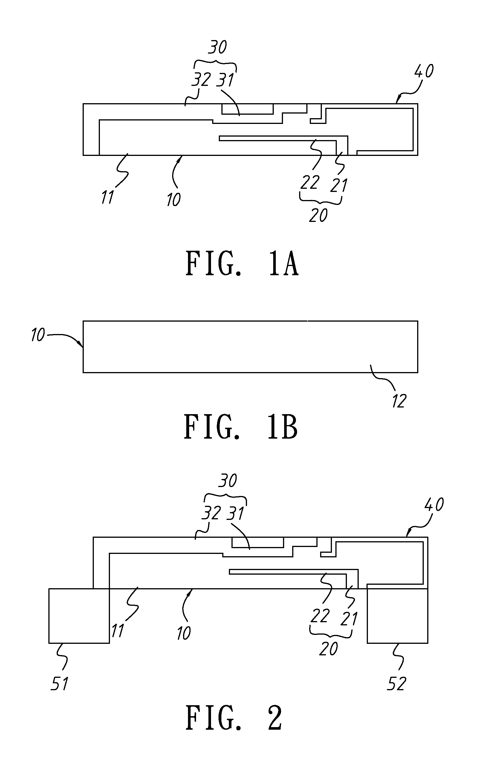
[0013]FIG. 1A and FIG. 1B are schematic diagrams showing a WWAN printed circuit antenna according to an embodiment of the invention.

[0014]A WWAN printed circuit antenna according to an embodiment of the invention includes a printed circuit board 10, a feeding monopole antenna 20, a first radiating monopole antenna 30, and a second radiating monopole antenna 40. The printed circuit board 10 includes a first surface 11 (shown in FIG. 1A) and a second surface 12 (shown in FIG. 1B) opposite to the first surface 11. In other words, the first surface 11 and the second surface 12 are two layout side surfaces of the printed circuit board 10.

[0015]The feeding monopole antenna 20, the first radiating monopole antenna 30, and the second radiating monopole antenna 40 are all disposed on a same side surface of the printed circuit board 10. In FIG. 1B, the feeding monopole antenna 20, the first radiating monopole antenna 30, and the second radiating monopole antenna 40 are all disposed on the fir...


PUM


Abstract

A WWAN printed circuit antenna includes three monopole antennas in the printed circuit board. Signals are fed in from the feed monopole antenna. The first and second radiating monopole antennas are actuated by the feed monopole antenna in an electromagnetic coupling way. Therefore, a three-dimensional structure derived from the planar inverted-F antenna can be replaced, and the limitation of space usage can be overcome.

Description

BACKGROUND OF THE INVENTION[0001]1. Field of Invention[0002]The invention relates to a WWAN printed circuit antenna and, more particularly, to a WWAN printed circuit antenna using three monopole antennas disposed on a same plane.[0003]2. Related Art[0004]Wireless wide area network (WWAN) is a wireless network whose transmission range may cross different cities or different countries. Since the range is large, a special service provider is usually needed to establish and maintain the entire network. Common people just use the WWAN by a terminal connection device. For example, global system for mobile communications (GSM) which most mobile phones use presently belongs to a kind of the WWAN. Consequently, via connections made by GSM operators, a high-speed data transfer rate can be provided, extensive data services including high-speed Internet access, large files downloading, streaming audio and video can be supported.[0005]Consequently, all conventional portable electronic devices ar...

Claims


Application Information

Patent Timeline
IPC IPC(8): H01Q5/00H01Q21/00H01Q1/38H01Q5/385
CPCH01Q1/243H01Q1/38H01Q5/385H01Q19/32H01Q9/42
Inventor LAI, MING-IUCHANG, WEI-SHENG
Owner ASUSTEK COMPUTER INC
Why Eureka
Try Eureka