Image forming apparatus
- Summary
- Abstract
- Description
- Claims
- Application Information
AI Technical Summary
Benefits of technology
Problems solved by technology
Method used
Image
Examples
first exemplary embodiment
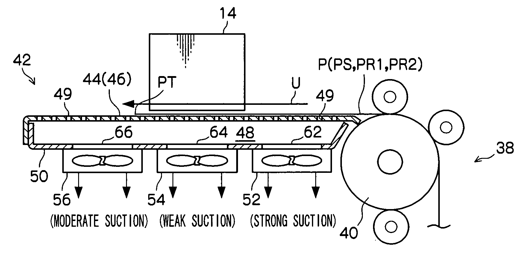
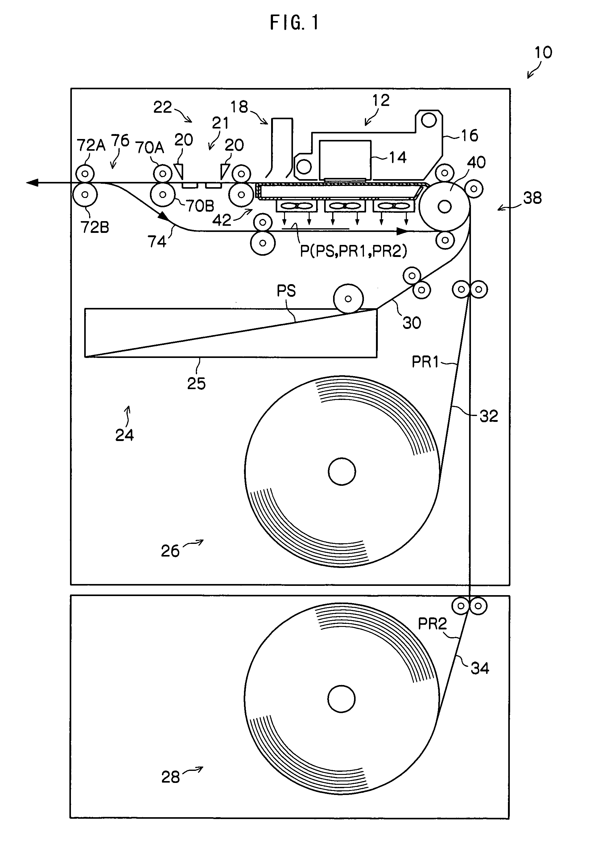
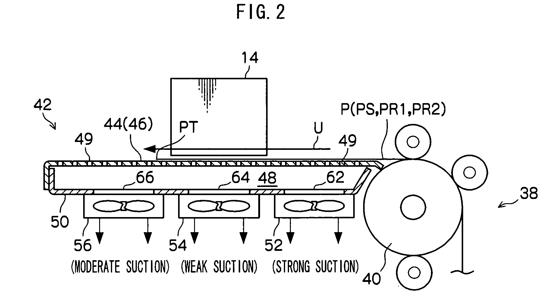
[0037]A first exemplary embodiment will be described. As shown in FIG. 1 and FIG. 2, an image forming apparatus 10 pertaining to the present exemplary embodiment is equipped with a formation unit 12 that forms an image on recording paper. The formation unit 12 includes an inkjet recording head 14 that ejects ink droplets onto the recording paper and a carriage 16 that holds the inkjet recording head 14. In the present exemplary embodiment, the image forming apparatus 10 is a color image forming apparatus that forms an image with the four colors of yellow (Y), magenta (M), cyan (C) and black (K), but the present exemplary embodiment is also applicable to a black-and-white image forming apparatus.
[0038]Further, the image forming apparatus 10 is equipped with a dryer 18 that supplies dry air to a recording surface side of the paper on which an image has been formed by the inkjet recording head 14 to solidify the ink droplets, a cutter 20 that cuts the recording paper and a main conveya...
second exemplary embodiment
[0064]Next, a second exemplary embodiment will be described. As shown in FIG. 4, an image forming apparatus 80 pertaining to the present exemplary embodiment has the same configuration as that of the image forming apparatus 10 pertaining to the first exemplary embodiment and is further equipped with a sensor 81 that detects the position of the conveyance direction leading edge of the recording paper P on the conveyance path 44 and a control unit 82 that controls the suction force of each of the suction fans 52, 54 and 56 on the basis of a signal received from the sensor 81. According to this configuration, the distribution of suction force along the conveyance direction U resulting from the suction fans 52, 54 and 56 is controlled by the control unit 82, and the distribution of suction force with which the recording paper P is adhered by suction onto the conveyance path 44 along the conveyance direction U is controlled by the control unit 82.
[0065]According to the present exemplary ...
third exemplary embodiment
[0066]Next, a third exemplary embodiment will be described. As shown in FIG. 5A and FIG. 5B, an image forming apparatus pertaining to the present exemplary embodiment has the same configuration as that of the image forming apparatus 10 pertaining to the first exemplary embodiment except that the image forming apparatus here is equipped with an air chamber forming member 90 instead of the air chamber forming member 50. On the air chamber forming member 90, partition wall portions 98 and 100 are disposed so as to form three air chambers 92, 94 and 96 from the upstream side in the conveyance direction U to the downstream side between the air chamber forming member 90 and the conveyance path forming member 46. Additionally, the suction fans 52, 54 and 56 are disposed so as to respectively suck the air chambers 92, 94 and 96 with negative pressure. Consequently, the suction fan 52 performs strong suction (suction whose flow rate is high), the suction fan 54 performs weak suction (suction...
PUM
 Abstract
Description
Claims
Application Information
 - R&D
- Intellectual Property
- Life Sciences
- Materials
- Tech Scout
- Unparalleled Data Quality
- Higher Quality Content
- 60% Fewer Hallucinations
Browse by: Latest US Patents, China's latest patents, Technical Efficacy Thesaurus, Application Domain, Technology Topic, Popular Technical Reports.
© 2025 PatSnap. All rights reserved.Legal|Privacy policy|Modern Slavery Act Transparency Statement|Sitemap|About US| Contact US: help@patsnap.com


