Eureka AIR delivers breakthrough ideas for toughest innovation challenges, trusted by R&D personnel around the world.

Droplet ejecting device

a technology of ejecting device and droplet, which is applied in the direction of printing, other printing apparatus, etc., can solve the problem of the interface separating function of the cleaning liquid to be shown

Inactive Publication Date: 2010-04-01
FUJIFILM CORP
View PDF5 Cites 28 Cited by
  • Summary
  • Abstract
  • Description
  • Claims
  • Application Information

AI Technical Summary

Benefits of technology

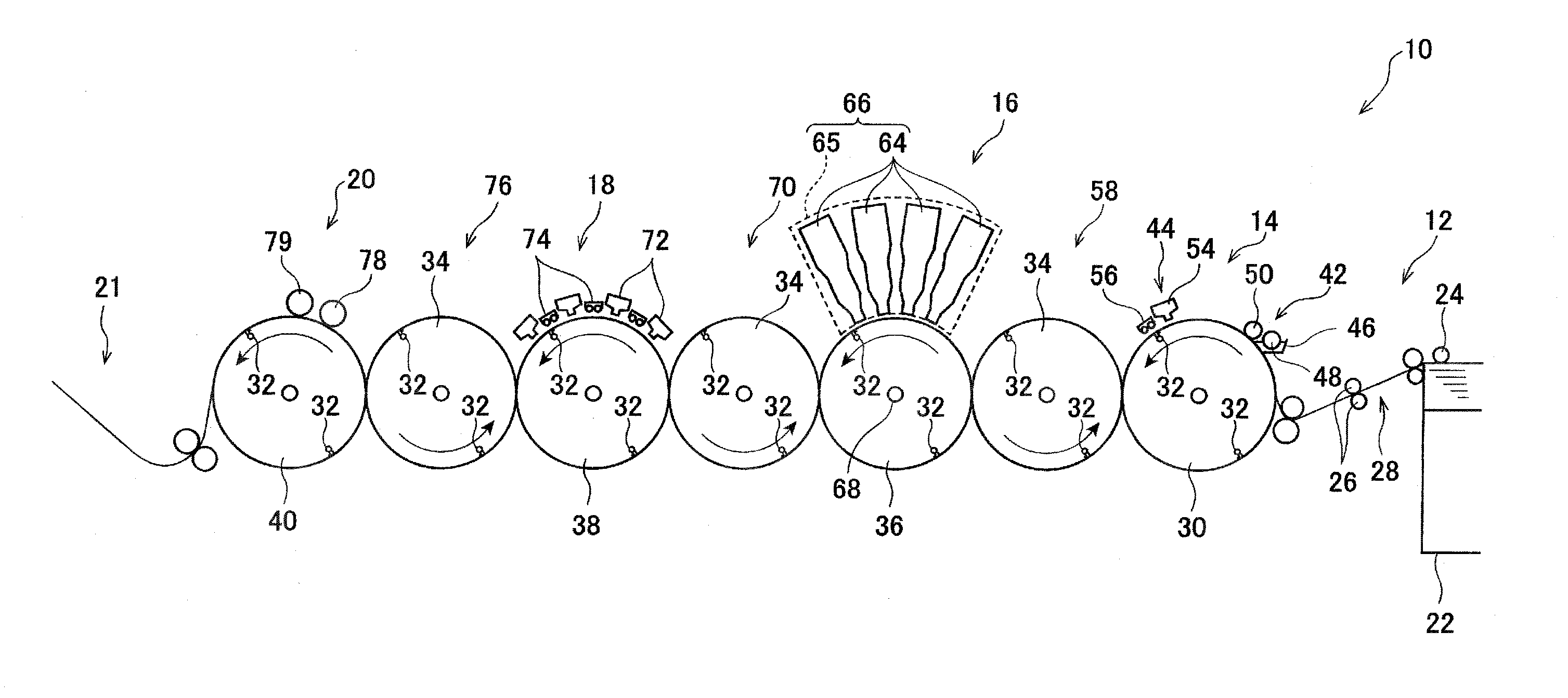
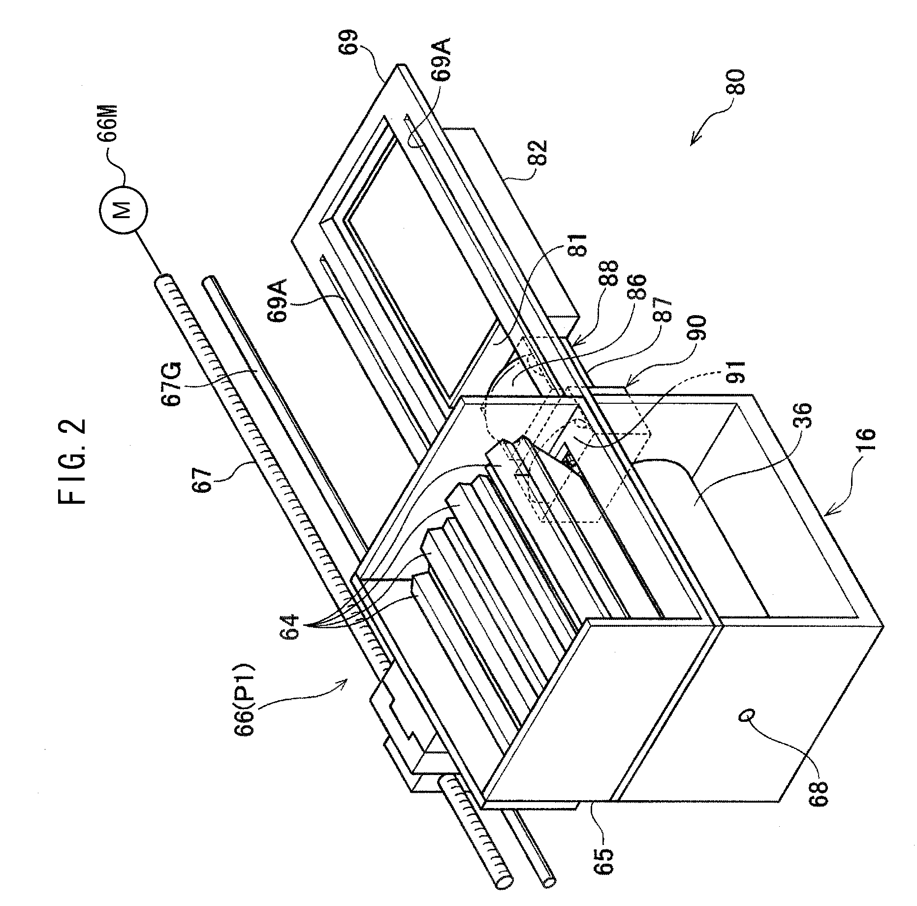
[0010]In the droplet ejecting device of the first aspect, the droplet ejecting head is moved relative to the applying member and the wiping member by the unit for movement. The applying member and the wiping member are disposed so as to be apart from one another. Accordingly, at the time of cleaning the nozzle surface, the cleaning liquid is applied to the nozzle surface by the applying member, and thereafter, the cleaning liquid can be wiped-off from the nozzle surface by the wiping member. By carrying out applying and wiping of the cleaning liquid separately in this way, as compared with a case in which the applying and wiping of the cleaning liquid are carried out simultaneously, the cleaning liquid can be made to stay adhered to the nozzle surface for a long time, and the interface separating function of the cleaning liquid can be exhibited.
[0012]By applying the cleaning liquid without contacting the nozzle surface in this way, damage to the nozzle surface can be prevented.
[0016]By making the rotating direction of the applying roller be the forward direction with respect to the direction of relative movement of the droplet ejecting head in this way, there is little friction with the nozzle surface, and damage to the nozzle surface can be prevented. Further, by making the rotating direction of the applying roller be the forward direction with respect to the direction of relative movement of the droplet ejecting head as described above, as compared with a case in which the applying roller is rotated in the reverse direction, there is little effect of the flow of the cleaning liquid on the meniscuses of the nozzles. Accordingly, the cleaning liquid can be applied to the nozzle surface without destroying the meniscuses, and poor ejecting due to the application of the cleaning liquid can be suppressed.
[0020]Due to such a structure, the applying and the wiping of the cleaning liquid can be carried out efficiently by movement of the recording head in one direction.
[0022]By providing such a unit for separation, after the cleaning liquid is applied by the applying member, the droplet ejecting head can be made to not contact the wiping member, and the cleaning liquid can adhere to the nozzle surface for a long time.

Problems solved by technology

However, in the technique disclosed in JP-A No. 2004-195908, because the applying and the wiping-off of the cleaning liquid are carried out simultaneously, it is difficult to cause the interface separating function of the cleaning liquid to be exhibited.

Method used


Image

  • Droplet ejecting device
  • Droplet ejecting device
  • Droplet ejecting device

Examples


example

[0097]By using DEGmBE (diethylene glycol monobutyl ether) of a viscosity of 20 CP as the cleaning liquid of the inkjet recording device of the present exemplary embodiment, a cleaning liquid film of 0.5 mm was formed on an applying roller whose diameter was φ 40 mm and whose rotational speed was 600 rpm, and the cleaning liquid was applied to the nozzle surfaces with the moving speed of the head unit being 80 mm / sec. A Toraysee (manufactured by Toray Industries, Inc.) was used as the wiping sheet, and was moved at 1.5 mm / sec in the direction opposite the head unit, and wiped-off the nozzle surfaces. The time from the application of the cleaning liquid until the wiping-off of the cleaning liquid by the wiping sheet was approximately 2 seconds. During this time, the cleaning liquid penetrated into the interface between the adhered matter and the nozzle surfaces, interface separation occurred, and the adhered matter was wiped-off well.


PUM


Abstract

A droplet ejecting device includes: a droplet ejecting head having a nozzle surface at which plural nozzles that eject droplets are formed; an applying member applying a cleaning liquid to the nozzle surface; a wiping member disposed so as to be spaced apart from the applying member, and moving relative to the nozzle surface while contacting the nozzle surface, and wiping-off the cleaning liquid applied to the nozzle surface; and a unit for moving that moves both the the droplet ejecting head, and the applying member and the wiping member, relative to one another.

Description

CROSS-REFERENCE TO RELATED APPLICATION[0001]This application claims priority under 35 USC 119 from Japanese Patent Application No. 2008-252201 filed on Sep. 30, 2008, the disclosure of which is incorporated by reference herein.BACKGROUND OF THE INVENTION[0002]1. Technical Field[0003]The present invention relates to a droplet ejecting device that forms an image on a recording medium by ejecting droplets toward the recording medium.[0004]2. Related Art[0005]Inkjet recording devices (droplet ejecting devices), that eject ink drops out from nozzles of an inkjet recording head (droplet ejecting head) and record an image on a recording sheet, are conventionally known. In order to keep the state of ejecting ink from the nozzles of the inkjet recording head good, the inkjet recording device is provided with a cleaning mechanism that wipes-off contaminating substances such as remaining ink (ink of increased viscosity), foreign matter (paper dust) and the like adhering to the nozzle surface.[...

Claims


Application Information

Patent Timeline
IPC IPC(8): B41J2/165
CPCB41J2/16535B41J2/16552B41J11/002B41J11/0015B41J2/16588B41J11/00216B41J11/0022
Inventor INOUE, HIROSHI
Owner FUJIFILM CORP
Why Eureka
Eureka Blog
Learn More