Speckle reduction in display systems that employ coherent light sources

a display system and light source technology, applied in semiconductor lasers, instruments, optical elements, etc., can solve the problems of reducing the quality of the displayed image, causing unwanted artificial effects from solid-state light sources,

Active Publication Date: 2010-04-01
TEXAS INSTR INC
View PDF7 Cites 41 Cited by
  • Summary
  • Abstract
  • Description
  • Claims
  • Application Information

AI Technical Summary

Benefits of technology

[0005]In one example, a speckle reduction method for use in a display system is disclosed herein, the method comprising: providing a light that is phase-coherent, wherein at least a phase-coherency of ...

Problems solved by technology

Regardless of certain superior properties over traditional light sources, solid-state light sources may produce unwanted artificial effects, one of which is speckle effect.
In display applications using coherent light...

Method used


Image

  • Speckle reduction in display systems that employ coherent light sources
  • Speckle reduction in display systems that employ coherent light sources
  • Speckle reduction in display systems that employ coherent light sources

Examples


Embodiment Construction

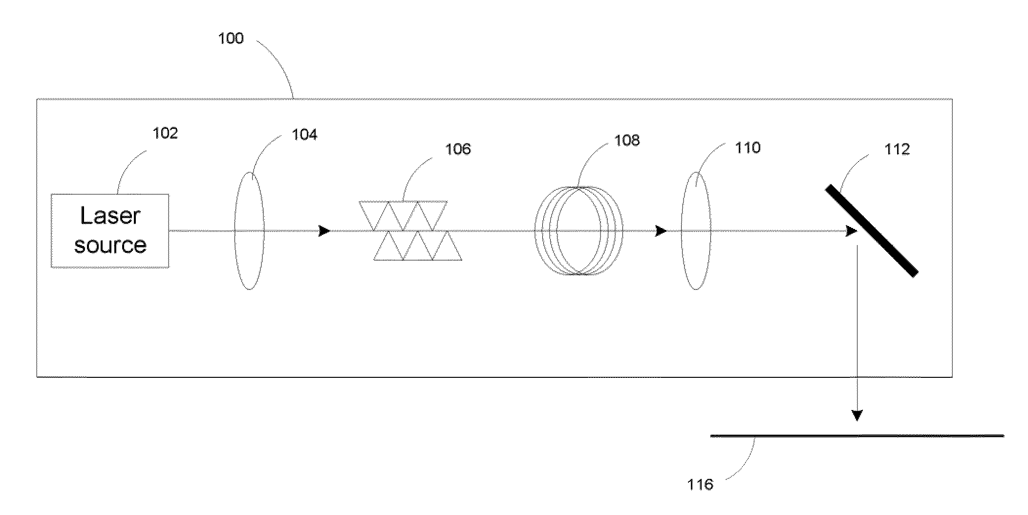
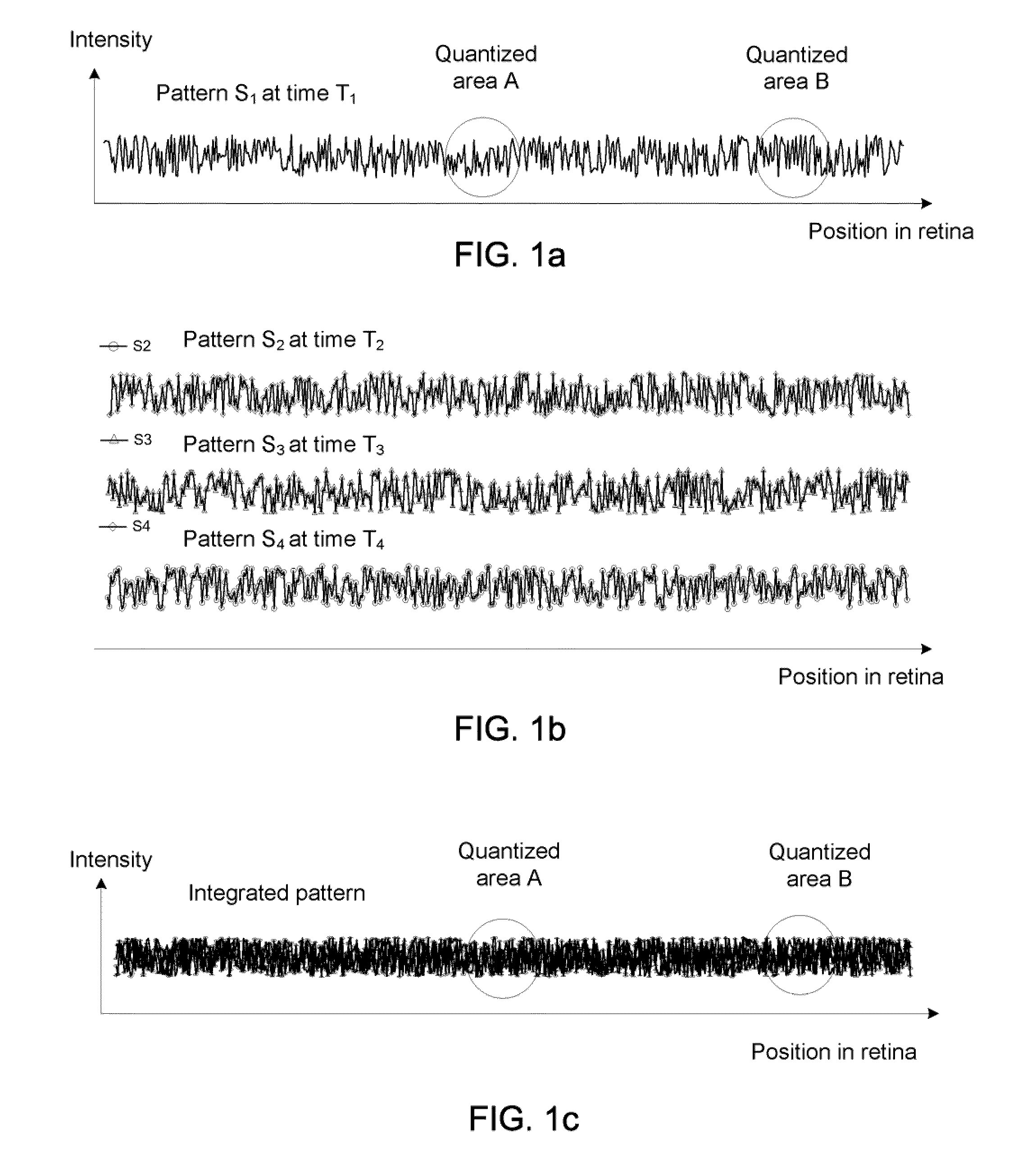
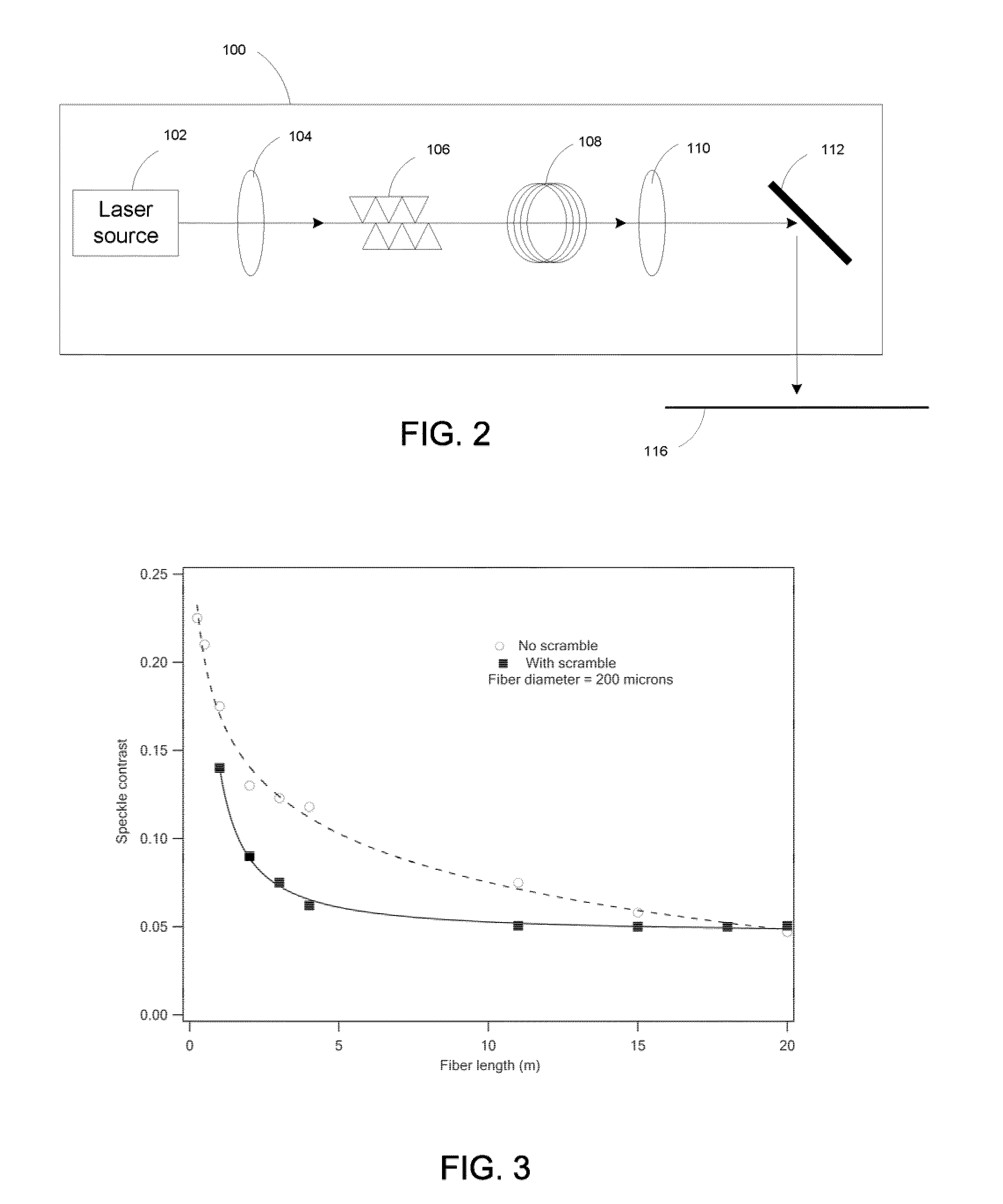
[0011]Disclosed herein is a method of reducing speckle effect in display systems that employ phase-coherent light. The speckle effect is reduced by using phase-coherent light that exhibits an instable profile, such as instable phase profile (e.g. mode hoping), during operation. The instable phase-coherent light is passed through a multi-mode optical fiber so as to trigger a variation of the instable profile, in particular, the phase profile, at the exit of the multi-mode optical fiber. The profile variation in turn creates a modification in the speckle pattern. The modified speckle pattern exhibits reduced contrast and appears as a noise background to the viewer. The method is capable of reducing the speckle effect without moving an element disposed in the optical axis of the display system or in the propagation path of the illumination light in the display system.

[0012]The speckle reduction method will be discussed in the following with particular examples wherein the speckle effec...


PUM


Abstract

Speckle effect in display system is reduced by utilizing the instability of phase-coherent light and the transmission of the instable phase-coherent light through a multi-mode optical fiber with a suitable length.

Description

TECHNICAL FIELD OF THE DISCLOSURE[0001]The technical field of this disclosure relates to the art of display systems; and more particularly to the art of speckle reduction in display systems that employ phase-coherent light.BACKGROUND OF THE DISCLOSURE[0002]In recent years, solid-state light sources and other narrow-wavelength-band and / or polarized light sources capable of producing visible light have drawn significant attention as alternative light sources to traditional light sources for use in imaging systems (such as projection systems). This attention has been due to many advantages of these light sources, such as compact size, greater durability, longer operating life, higher efficiency, and lower power consumption. For example, solid state sources such as LASERs, light-emitting-diodes (LEDs), and pumped non-linear optical crystals are increasingly being used or considered for use in imaging systems, e.g. imaging systems that employ one or more light valves each of which compri...

Claims


Application Information

Patent Timeline
IPC IPC(8): G02B26/00H01S3/13G02F1/035H01S3/10
CPCG02B27/48H04N9/3129H01S5/0652H01S3/005
Inventor GRASSER, REGISSHI, HONGQINBARTLETT, TERRY A.
Owner TEXAS INSTR INC
Why Eureka
Try Eureka