
Backlash reducing device for an objective lens assembly

a technology of backlash reduction and objective lens, which is applied in the direction of mountings, instruments, optics, etc., can solve the problems of reducing the efficiency of the objective lens assembly, introducing backlash between the housing and the lens cell, disassembly and repair, etc., and reducing backlash. , the effect of reducing backlash

Active Publication Date: 2010-04-01
ELBIT SYSTEMS OF AMERICA LLC
View PDF7 Cites 6 Cited by
  • Summary
  • Abstract
  • Description
  • Claims
  • Application Information

AI Technical Summary

Benefits of technology

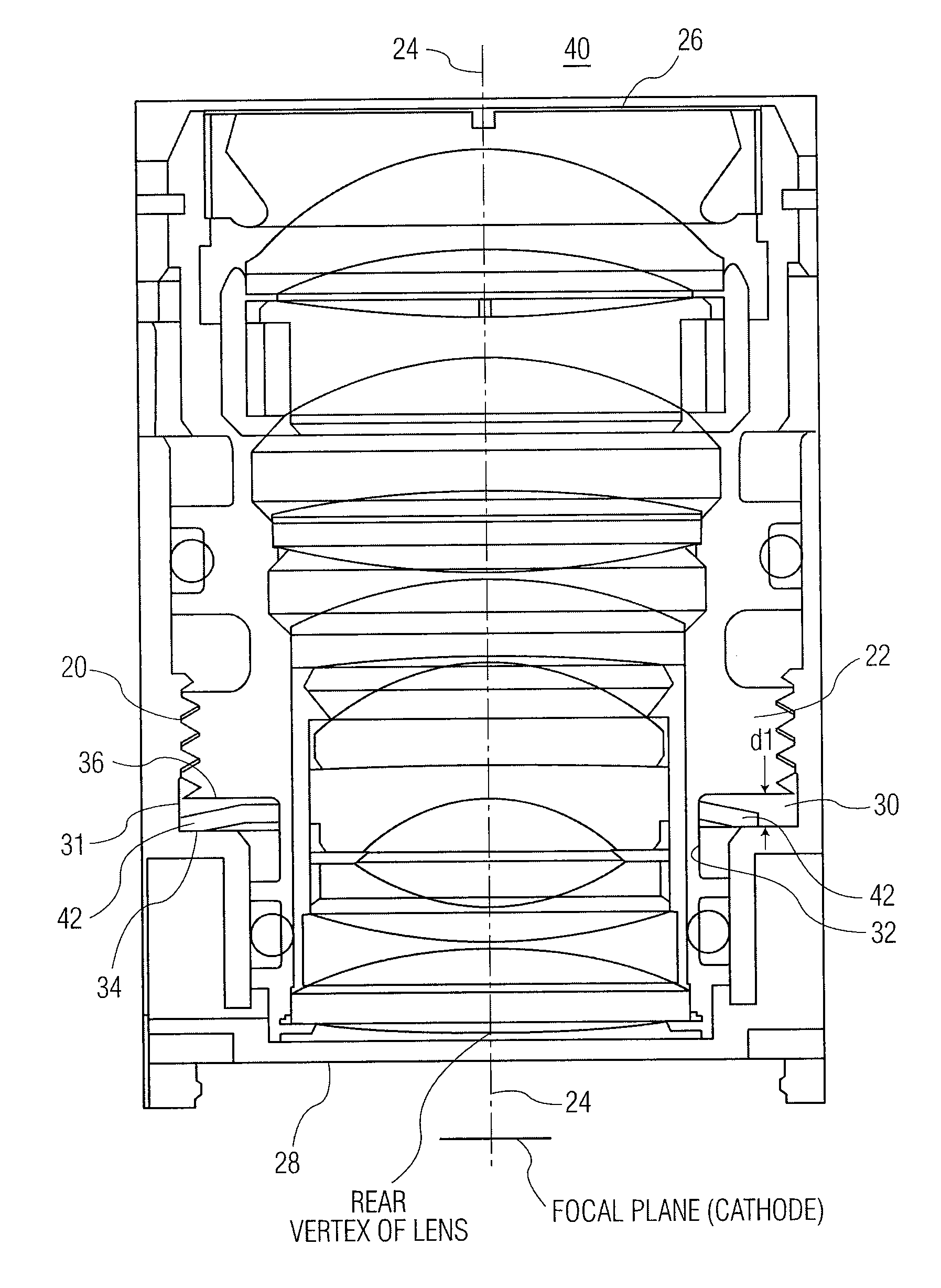
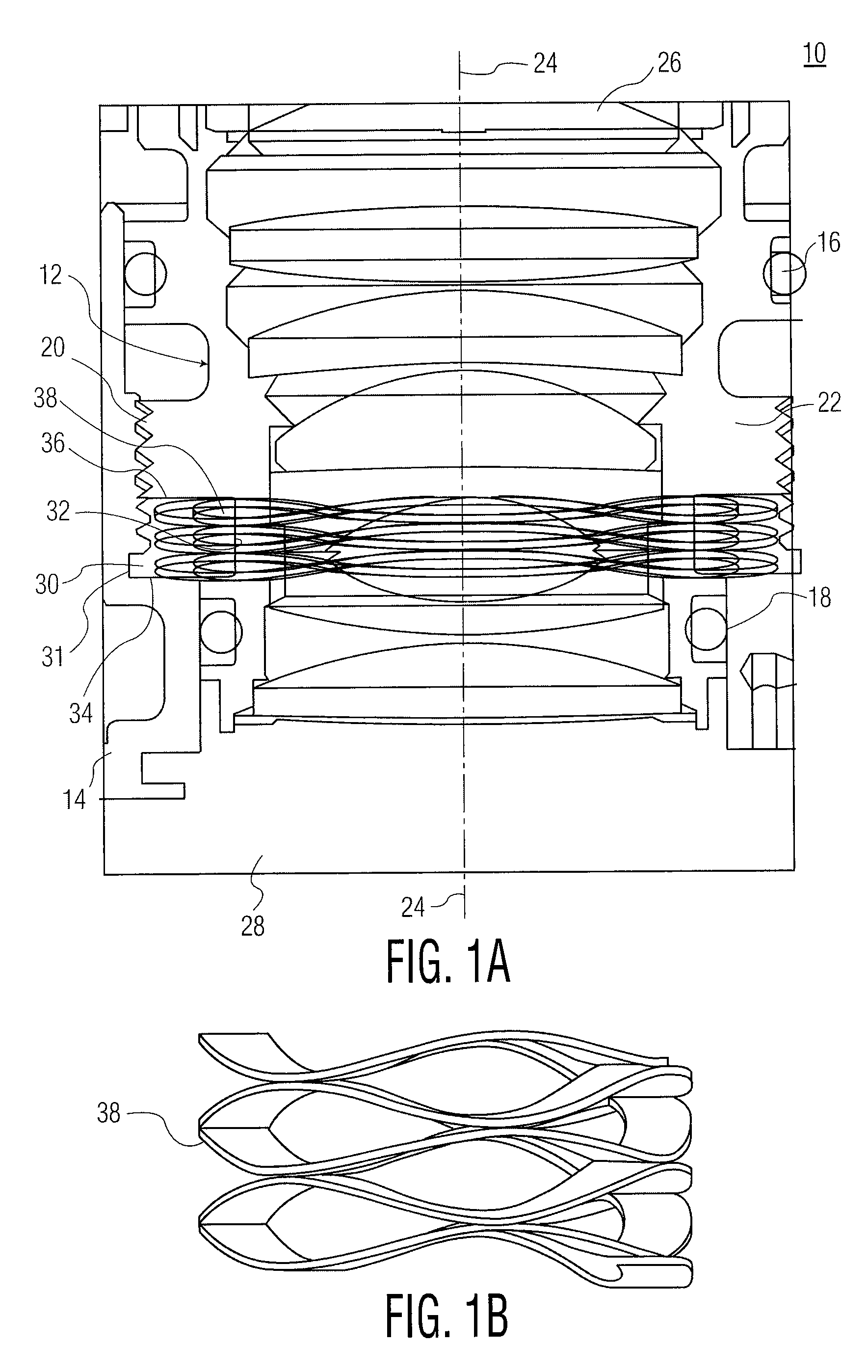
[0005]The present invention is directed to an objective lens assembly including an objective lens cell having a threaded portion, an optical bench having a mating threaded portion for receiving the objective lens cell, and a biasing element. The biasing element reduces backlash between the objective lens cell and the optical bench. The biasing element may be either a belleville washer, a snap-ring washer, or any other type of washer. The biasing element is configured for a relaxed mode of operation and a compressed mode of operation. In the relaxed mode, the biasing element is inactive, and in the compressed mode, the biasing element reduces backlash between the objective lens cell and the optical bench.
[0007]Another embodiment of the present invention includes an objective lens assembly for night vision goggles including an objective lens cell having a threaded portion, an optical bench having a mating threaded portion for thread ingly receiving the objective lens cell, and a biasing element. The biasing element reduces backlash between the objective lens cell and the optical bench. The biasing element may be either a belleville washer or a snap-ring washer. The biasing element is configured for a relaxed mode of operation and a compressed mode of operation. In the relaxed mode, the biasing element is inactive, and in the compressed mode, the biasing element reduces backlash between the objective lens cell and the optical bench.

Problems solved by technology

Because of the need for a loose fit between the mated threads, the coupling between the housing and the lens cell introduces backlash.
Backlash causes focus and resolution errors in the objective lens assembly which may require disassembly and repair.

Method used


Image

  • Backlash reducing device for an objective lens assembly
  • Backlash reducing device for an objective lens assembly
  • Backlash reducing device for an objective lens assembly

Examples


Embodiment Construction

[0022]Certain terminology is used herein for convenience only and is not to be taken as a limitation on the present invention. The terminology includes words specifically mentioned, derivatives thereof and words of similar import. As used herein, the term “input” (also referred to as near focus) is defined to mean a direction farther from a user when the objective lens assembly is in a use position as described herein and “output” (also referred to as focus at infinity) is defined to mean a direction closer to the user when the objective lens assembly is in a use position as described herein.

[0023]While this invention is susceptible of embodiment in many different forms, there is shown in the drawings and will herein be described in detail, several specific embodiments, with the understanding that the present disclosure is to be considered as an exemplification of the principles of the invention and is not intended to limit the invention to the embodiments illustrated.

[0024]Referrin...


PUM


Abstract

An objective lens assembly for night vision goggles including an objective lens cell having a threaded portion, an optical bench having a mating threaded portion for receiving the objective lens cell, and a snap-ring washer for reducing backlash between the objective lens cell and the optical bench. The objective lens cell includes a first wall radially extending away from an axial neck portion, the optical bench includes a second wall radially extending toward the axial neck portion and oriented substantially parallel to the first wall, and the snap-ring washer circumferentially surrounds the axial neck portion of the objective lens cell. The biasing element is configured for a relaxed mode of operation and a compressed mode of operation. In the relaxed mode, the snap-ring washer is inactive, and in the compressed mode, the snap-ring washer reduces backlash between the lens cell and the optical bench.

Description

FIELD OF THE INVENTION[0001]This invention relates, generally, to objective lens assemblies. More specifically, the present invention relates to an objective lens assembly including a biasing device for reducing backlash between the threads of an objective lens cell and mating threads of its housing.BACKGROUND OF THE INVENTION[0002]Objective lens assemblies may be incorporated into a number of devices, such as night vision devices or other optical systems. Each lens assembly typically includes an objective lens cell and a housing, where the objective lens cell is inserted in a tubular section of the housing. A set of female threads on the inner tubular section of the housing mates corresponding male threads on the outer surface of the lens cell. By translating the objective lens cell relative to the housing, along an optical axis, the objective lens assembly focuses upon an external subject. The threaded coupling between the objective lens cell and the housing has a tolerance suffic...

Claims


Application Information

Patent Timeline
IPC IPC(8): G02B7/02
CPCG02B7/021G02B7/026
Inventor NEFF, TODD
Owner ELBIT SYSTEMS OF AMERICA LLC
Learn More