
Method and apparatus for seismic exploration

a technology of seismic exploration and methods, applied in seismic energy generation, seismicology, instruments, etc., can solve the problems of significant deleterious effects on the return energy level, limited use of vibration sources on land, and little useful recorded reflection energy from the interface, so as to facilitate compensation and suppress ground roll interference.

Inactive Publication Date: 2010-04-01
MANATT JR JAMES C
View PDF26 Cites 34 Cited by
  • Summary
  • Abstract
  • Description
  • Claims
  • Application Information

AI Technical Summary

Benefits of technology

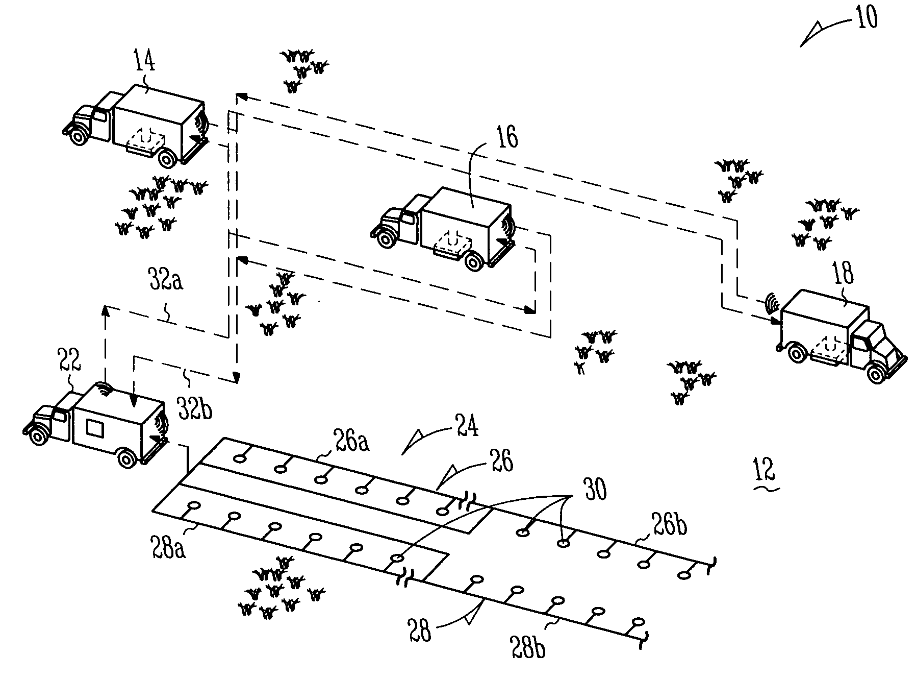
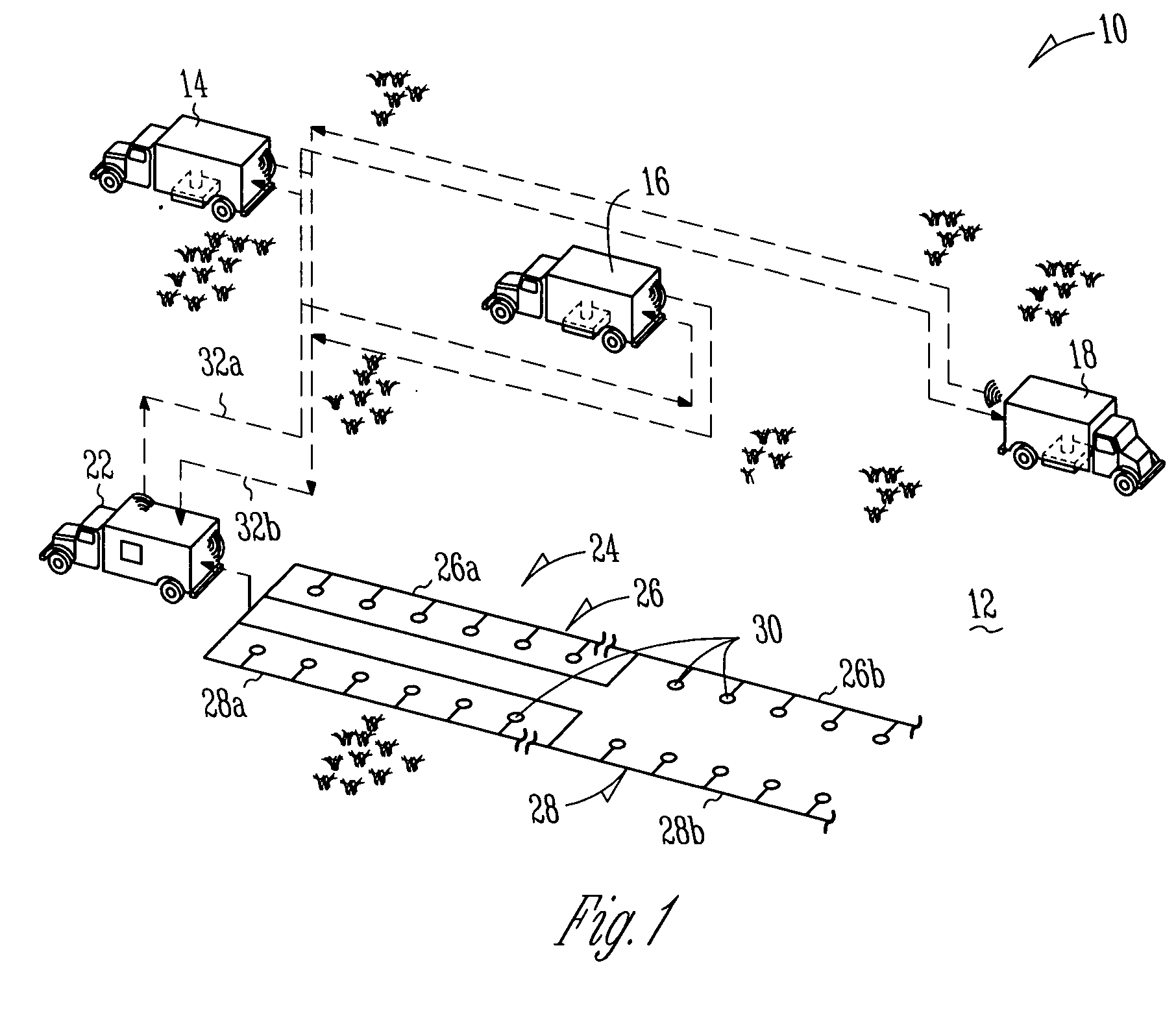
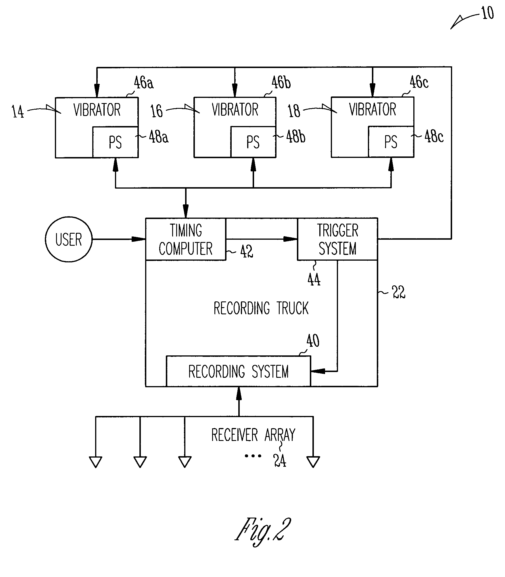
[0017]The present invention includes methods of seismic exploration which facilitate compensation for various surface and subsurface geological considerations. For example, in some examples of the invention, a seismic source array may be actuated in order to direct the main axis of an energy beam resulting from the source array beam in a desired direction. This may be used to direct the beam either based upon subsurface formations of interest, and/or to compensate for surface contours or characteristics. The energy beam may be directed through use of delayed triggers of multiple seismic sources, defining an actuation interval between the sources. In some preferred examples, the present inventio

Problems solved by technology

Vibratory sources used on land are limited to placement on the earth's surface.
This limitation combined with the current practice of simultaneous source initiation, results in the pointing direction of the resulting source energy beam being perpendicular to the surface.
This can have significant deleterious effects on returning energy levels at the detectors for certain configurations of subsurface reflecting interfaces.
However, when such subsurface interfaces are not generally parallel to the surface, but are oriented in such a way as to reflect the main energy of the source beam in a direction away from the detecting sensors, little useful recorded reflection energy from the interfaces may result.
A second deleterious effect results from the placement of sources of any type on the earth' surface.
This can result in the generation of unwanted horizontally traveling surface waves, often referred to as “ground roll.” These surface waves are characterized by low frequency content and low velocity, and often arrive at the detectors at the same time as reflection energy from the deeper parts of the earth's interior.
Receivers in the array may be spaced and deployed along directions that produce destructive interference of ground roll when the detected signals from the individual receivers in the array are summed together.
Any deviation from this ideal placement will result in degradation of the suppression of ground roll effects.
This approach still suffers from the problems and effects from source placement errors, and the ground roll suppression inefficiencies that result.
However, this vertical direction of the beam can lead to less than optimal results where the subsurface formations are not parallel to the surface.
Another possible source of error in land-based seismic exploration systems is that of inaccurate placement of the sources forming the ground roll suppressing array.
Current practice does not generally provide for surveying each individual vibratory source location in advance (currently a costly and time-consuming process), to provide sufficient information to assure the ability to place each vibratory source correctly.
This problem can be further complicated by unavoidable obstructions and other surface conditions that prevent the placement of one or more sources of the array in the intended location.
Such source placement errors limit the ability of the source array to optimally suppress ground roll.
Additionally, in many instances, the configuration of the earth being seismically surveyed will not lend itself to such exact placements.

Method used


Image

  • Method and apparatus for seismic exploration
  • Method and apparatus for seismic exploration
  • Method and apparatus for seismic exploration

Examples


Embodiment Construction

[0033]In the following description, numerous specific details are set forth. However, it should be understood that embodiments of the invention may be practiced without these specific details. In other instances, well-known circuits, structures and techniques have not been shown in detail in order not to obscure the understanding of the invention. In this description, references to “one embodiment” or “an embodiment” mean that the feature being referred to is, or may be, included in at least one embodiment of the invention. Separate references to “an embodiment” or “one embodiment” in this description are not intended to refer necessarily to the same embodiment; however, neither are such embodiments mutually exclusive, unless so stated or except as will be readily apparent to those of ordinary skill in the art. Thus, the present invention can include any variety of combinations and / or integrations of the embodiments described herein, as well as further embodiments as defined within ...


PUM


Abstract

The disclosure identifies method and apparatus for seismic exploration which may be used to provide improved positioning of land-based seismic sources in an array. Also described are methods which make use of the improved positioning to allow, in some examples, improved direction or distribution of the energy beam resulting from actuation of the sources. Some methods make use of the described techniques to steer the energy beam; and in some cases at each source or a distribution location, multiple shots will be taken to distribute the beam in multiple orientations relative to the central source point.

Description

BACKGROUND OF THE INVENTION[0001]The present invention relates generally to methods and apparatus for seismic exploration; and more specifically relates to improved methods and apparatus for the initiation of seismic sources during such exploration. The present invention is applicable to all land based sources but offers particular advantages when applied to initiation of vehicle mounted surface sources via radio-controlled signals such as vibratory sources.[0002]The basic principal of seismic surveying, whether on land or at sea, is to periodically actuate man-made sources to produce seismic energy that propagates into the earth. This propagating seismic energy is partially reflected, refracted, diffracted and otherwise affected by one or more geologic structures within the earth. The affected seismic energy is detected by sensors, or “receivers,” placed at or near the earth's surface or the air-sea interface. The receivers are attached to recording instruments that make a permanen...

Claims


Application Information

Patent Timeline
IPC IPC(8): G01V1/06
CPCG01V1/006G01V1/003
Inventor MORGAN, THOMAS R.MANATT, JAMES C.
Owner MANATT JR JAMES C
Learn More