

Fiber optic connector assembly employing fiber movement support and method of assembly
a technology of movement support and fiber optic connector, which is applied in the direction of optics, instruments, optical light guides, etc., can solve the problems of high insertion loss, achieve the effect of avoiding or reducing kinking or bending of optical fibers, and being more rigid
- Summary
- Abstract
- Description
- Claims
- Application Information
AI Technical Summary
Benefits of technology
Problems solved by technology
Method used
Image

Examples
Embodiment Construction
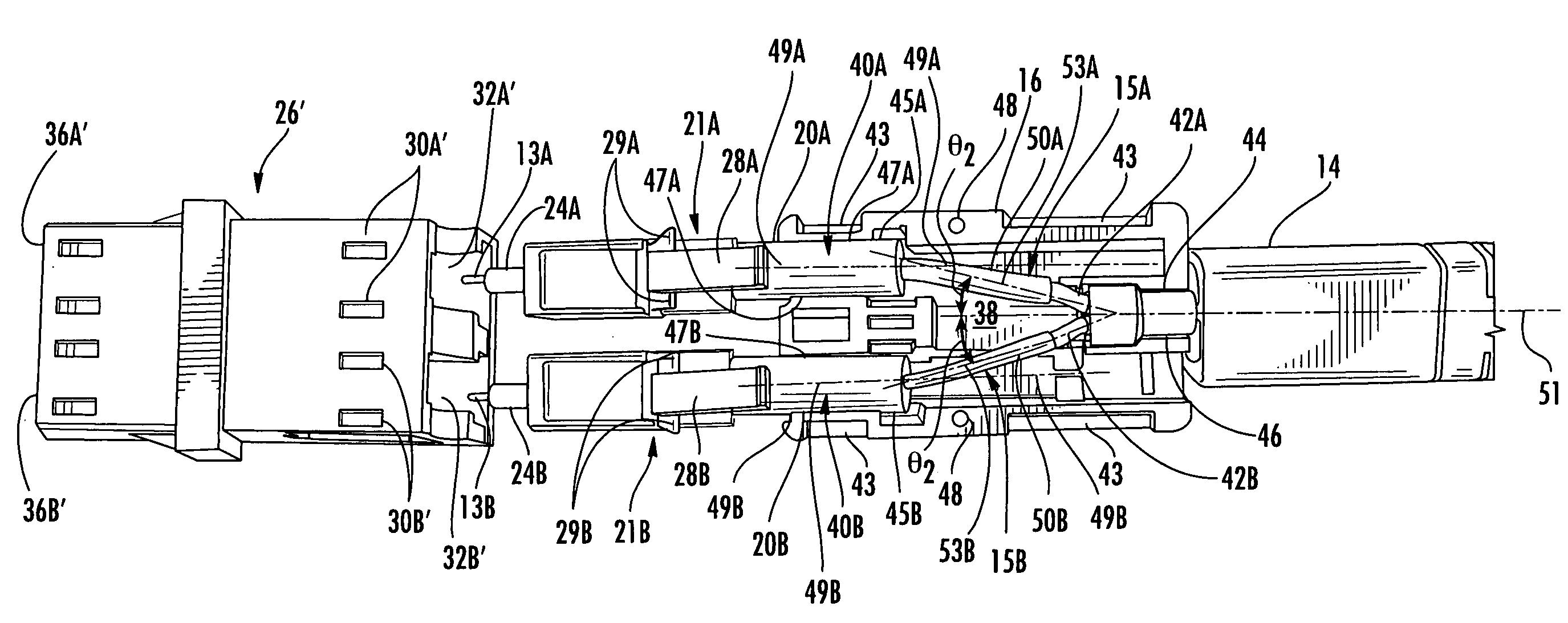
[0011]Embodiments of the present invention include a fiber optic connector assembly employing one or more fiber movement supports. The one or more fiber movement supports are each disposed around one or more optical fibers contained inside an optical connector housing. The one or more fiber movement supports are configured to inhibit sharp bends from occurring in the one or more optical fibers as a result of a force exerted on the one or more optical fibers in a direction angled to the axis of the one or more optical fibers. The fiber movement support is more rigid than an optical fiber. Thus, when a force is exerted on an optical fiber in a direction angled to the axis of the optical fiber supported by the fiber movement support, the force is directed to the fiber movement support. The fiber movement support translates the non-axial force in a direction towards the longitudinal axis of the optical fiber. This causes the optical fiber to be pushed back towards and / or into the fiber ...
PUM
 Abstract
Description
Claims
Application Information