Minimally invasive bone miller apparatus

a miller and minimally invasive technology, applied in the field of artificial joint prostheses, can solve the problems of affecting the quality of bone preparation,

Active Publication Date: 2010-04-01
DEPUY PROD INC
View PDF101 Cites 22 Cited by
  • Summary
  • Abstract
  • Description
  • Claims
  • Application Information

AI Technical Summary

Problems solved by technology

Broaches or rasps, when used for bone preparation, have limitations.
One such limitation is the risk of fracture during broaching.
Since broaching is done by pounding the broach into the bone, the bone tends to fracture.
Additionally, both broaches and rasps suffer from a tendency to be deflected by harder sections of bone so that they do not create as precise a triangular cavity as can be created by a miller system.
A limitation of milling systems today is that they are typically formed so that the drive shaft extends at an angle relative to the remainder of the frame from the end of the miller cutter machining the bone.
However, to accommodate this miller, it is necessary to make a fairly large incision which may be undesirable for cosmetic or other reasons.
Therefore, not only is the input power direction restricted, but this, in turn, restricts the angle at which the reamer may be used on a patient.
However, as other instruments only require about one and a half to two inches, it is not ideal to use a miller that requires a larger incision.

Method used


Image

  • Minimally invasive bone miller apparatus
  • Minimally invasive bone miller apparatus
  • Minimally invasive bone miller apparatus

Examples


Embodiment Construction

[0021]Embodiments of the present invention and the advantages thereof are best understood by referring to the following descriptions and drawings, wherein like numerals are used for like and corresponding parts of the drawings.

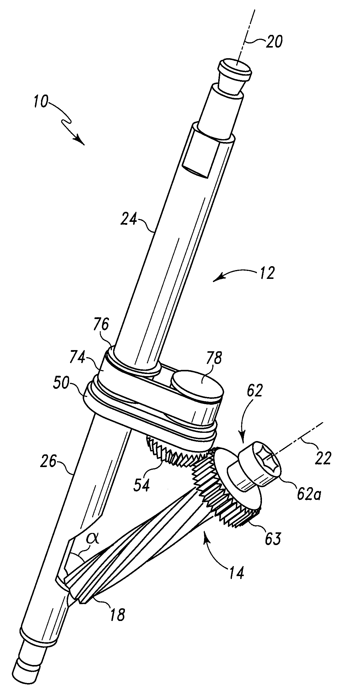
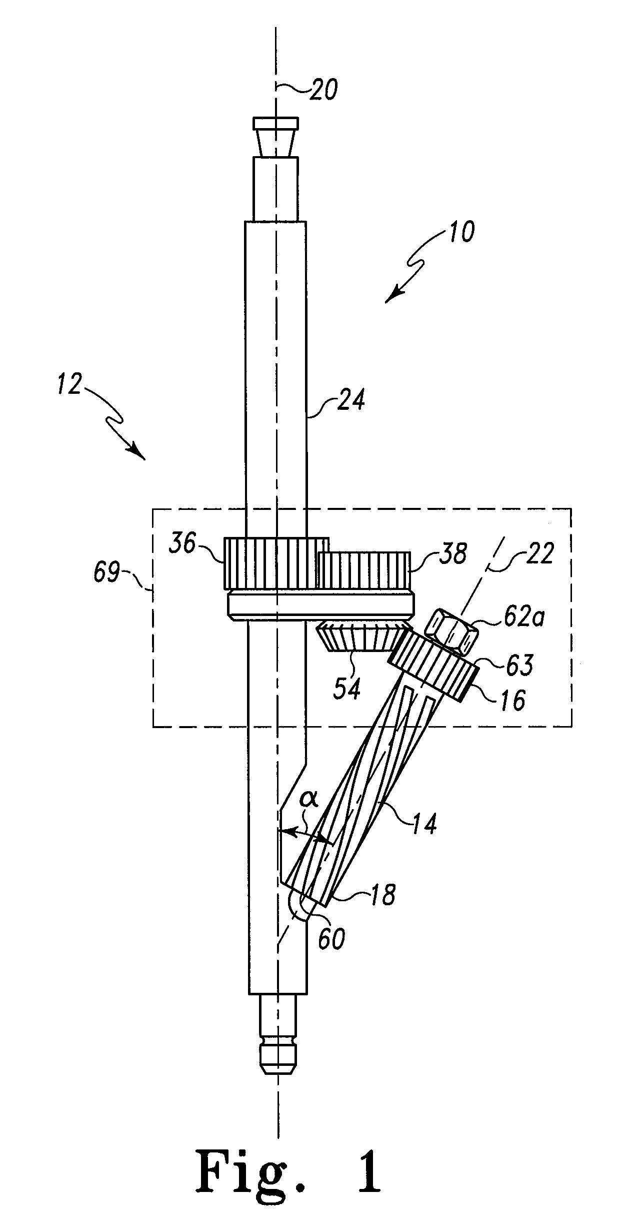
[0022]The disclosed calcar miller assembly 10 allows a surgeon to machine (mill) bone through a smaller incision compared to existing surgical instruments. As shown in FIG. 1, the miller assembly 10 includes a frame 12 and a miller cutter 14 that is coupled to the frame 12 at both a proximal end 16 and a distal end 18. The frame 12 includes a longitudinal axis 20. The miller cutter 14 also has a longitudinal axis 22 that is offset at an angle α from the longitudinal axis 20 of the frame 12. The angle α is greater than 0 degrees. In some embodiments, the angle α is between about 30 and about 60 degrees. In some embodiments, the angle α is between about 40 degrees and about 50 degrees.

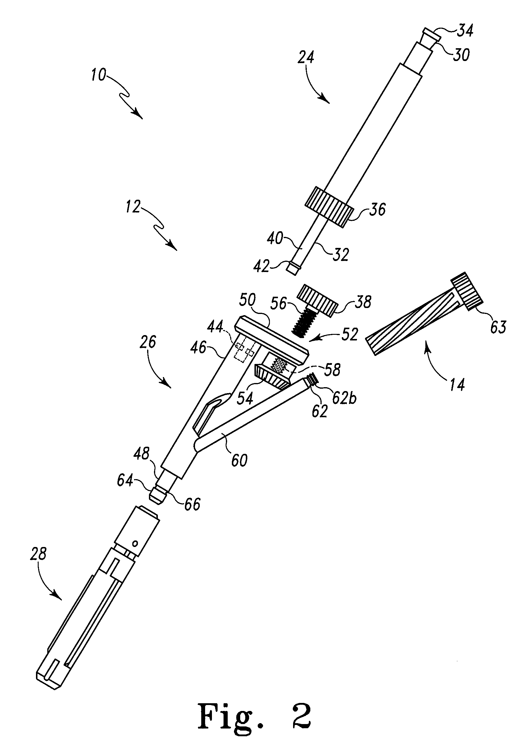
[0023]Turning now to FIG. 2, an exploded view of the calcar miller assembly 10...


PUM


Abstract

A miller assembly for creating a cavity in a bone. The cavity has a cross section which has a generally triangular profile having a first side generally parallel with an axis of the bone and a second side forming an acute angle with the first side, and is contiguous with a pre-existing conical cavity in the bone. The miller assembly includes a cutter and a frame for carrying the cutter. The frame includes a connection portion having a longitudinal axis and a cutter mount for mounting the cutter at a first angle approximating the acute angle with respect to the longitudinal axis of the connection portion. The cutter mount extends at the first angle from the longitudinal axis of the connection portion and is configured to receive a portion of the cutter and maintain the received cutter oriented at the first angle during rotation. The frame further includes a handle configured to form a portion of a drive joint for coupling the frame to a drill, the handle having a longitudinal axis. The longitudinal axis of the handle is coincident with the longitudinal axis of the frame.

Description

TECHNICAL FIELD OF THE INVENTION[0001]This invention relates to the field of artificial joint prostheses and, in particular, to an improved instrument for machining a precise cavity in bone for receiving a prosthesis.BACKGROUND OF THE INVENTION[0002]For implantation of prosthetic stems, such as hip stems, accurate preparation of the bone or intramedullary canal is extremely important in order to guarantee good contact between the prosthesis stem and the bone. The underlying concept behind precise preparation is that a precise bone envelope reduces the gaps between the implant (i.e. prosthesis or prosthetic component) and the bone, thereby improving the initial and long-term bone ingrowth / fixation. The bone canal is presently prepared for implantation of a prosthetic stem by drilling and reaming a resected end of a bone, such as a femur, and then preparing an area adjacent the drilled hole to provide a seat for the prosthetic stem or a proximal sleeve coupled to the stem of a modular...

Claims


Application Information

Patent Timeline
Patent Type & Authority Applications(United States)
IPC IPC(8): A61B17/00
CPCA61B17/1668A61B17/1675A61F2/367A61B17/175A61B17/1684
Inventor SACKETT, SAMUEL G.JOHNSON, BRIAN P.OWEN, SAMUEL B.MCCLEARY, LARRY G.
Owner DEPUY PROD INC
Why Eureka
Try Eureka