
Quickly Slideable And Incrementally Adjustable Barrier

a technology of incremental adjustment and sliding, applied in the field of barriers, can solve the problems of increasing the effective length of the gate or barrier, the gate or barrier is too long and may not fit in such a doorway, the gate or barrier may bend and break, or the mechanism may break, etc., to achieve the effect of easy and quick axial sliding, simple operation, and easy operation

Active Publication Date: 2010-04-08
CARLSON PET PRODS
View PDF19 Cites 32 Cited by
  • Summary
  • Abstract
  • Description
  • Claims
  • Application Information

AI Technical Summary

Benefits of technology

[0017]An advantage of the present invention is that it fits in relatively large doorways and relatively small doorways and, regardless of the size of the doorway, can be incrementally pressure fit to the large or small doorway. In other words, the present barrier is expandable from a relatively small length to a relatively great length and, regardless of how much the barrier has been expanded, the barrier can be incrementally expanded so as to become pressure fit securely between the two locations to which the barrier is engaged.
[0018]Another advantage of the present invention is that it is simple to use. There is but one mechanism to operate to expand the barrier in some embodiments and but two mechanisms to operate in other embodiments.
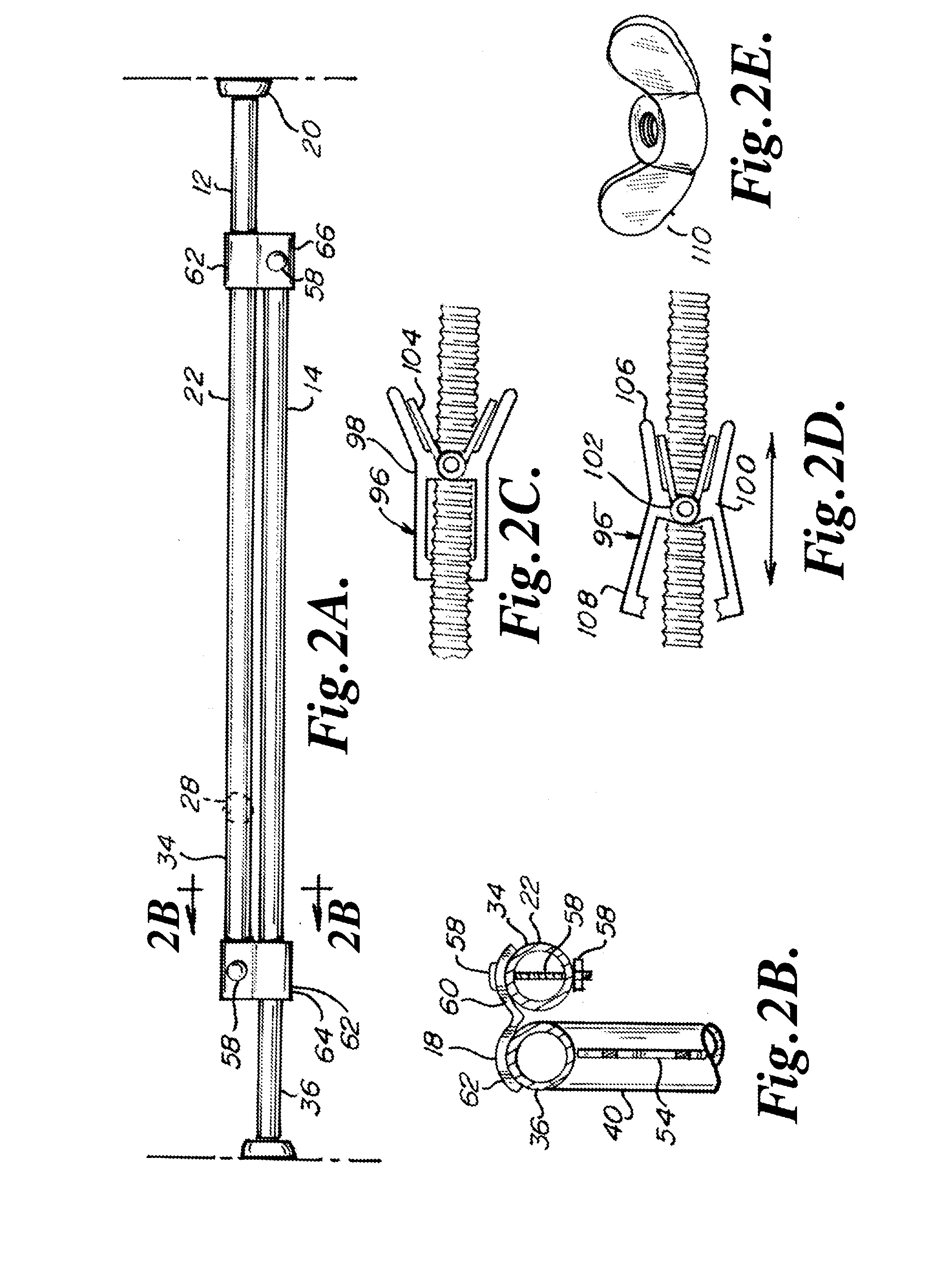
[0019]Another advantage of the present invention is that it may be operated quickly. One feature contributing to this advantage is the slide nut. Instead of turning a conventional nut along the entire length of the threaded rod, the slide nut can be quickly slid axially along the rod to the desired position and then tightened at the desired position. Another feature contributing to this advantage is the jawed piece that incrementally expands the two partitions relative to each other. The jawed piece, when pinched open, can easily and quickly slide axially on the threaded rod. When pinched open, the jawed piece does not engage the threads of the threaded rod and thus can travel at will back and forth on the threaded rod. When closed, and the jawed piece is normally biased closed, the jawed piece is turnable on the threaded rod, brings pressure to bear on the end of the tube receiving the threaded rod and thereby expands the partitions relative to each other. Another feature contributing to this advantage is the slide that can quickly be hand pushed to the desired location, whereupon a lift / drop button of the slide fixes the slide in place, whereupon a threaded member of the slide incrementally expands the partitions to a pressure fit against opposing members such as door jambs.
[0020]Another advantage of the present invention is that the present barrier is inexpensive to manufacture. For example, there are no complicated mechanisms to produce. Also, the manufacturing process for the first partition frame can be used for the second partition frame because the frames are identical to each other.
[0021]Another advantage of the present invention is that the present barrier can be expanded to about twice its shelf or fully closed size. In other words, the barrier can be sold in a box that takes up a minimum of shelf space and then, when taken out of the box, can be utilized at such a relatively small size or can be expanded to about twice its length to be utilized at such a relatively large size or can be utilized at any size therebetween.

Problems solved by technology

This is problematic because some doorways are more narrow than other doorways.
Therefore, utilization of one notch may engage the gate or barrier too loosely in a certain doorway, while utilization of the next notch in line may increase the effective length of the gate or barrier such that the gate or barrier is too long and may not fit in such a doorway at all.
Or, if forced to fit in the doorway, the gate or barrier may bend and break or the mechanism may break.

Method used


Image

  • Quickly Slideable And Incrementally Adjustable Barrier
  • Quickly Slideable And Incrementally Adjustable Barrier
  • Quickly Slideable And Incrementally Adjustable Barrier

Examples


Embodiment Construction

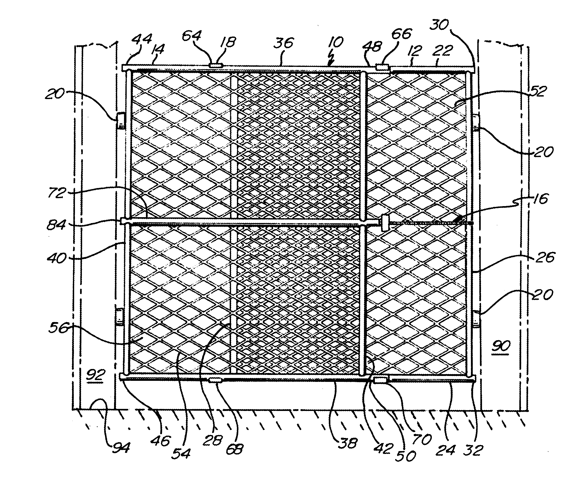
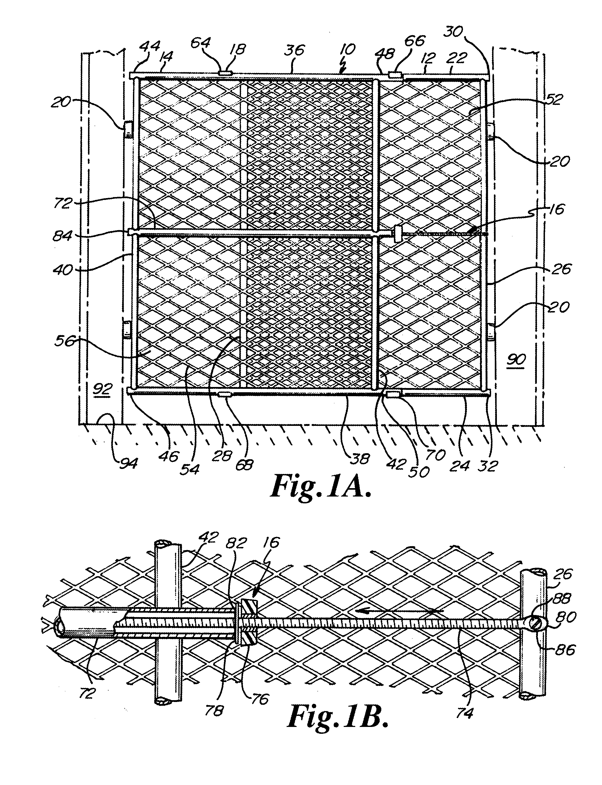
[0048]As shown in FIG. 1, the present quickly slideable and incrementally adjustable barrier is indicated by reference numeral 10. The barrier 10 generally includes a first partition 12, a second partition 14, an adjusting and pressurizing mechanism 16, guides 18 running to and between the first and second partitions 12, 14, and bumpers 20 on an outer end of each of the partitions 12, 14.

[0049]First partition 12 includes an upper member 22, a lower member 24, an outer end member 26, and an inner end member 28. Members 22, 24, 26 and 28 are preferably steel and tubular. Members 22, 24 run parallel to each other and preferably run horizontally when the barrier 10 is in use. Members 26, 28 run parallel to each other and preferably run vertically when the barrier 10 is in use. Members 22, 24 are preferably disposed at right angles to members 26, 28, and the junctions of such members 22, 24, 26, 28 are welded. End members 24, 26 run to and between upper and lower members 22, 24. Upper me...


PUM


Abstract

A barrier for the inside of a home. The barrier includes two partitions that slide relative to each other to increase and decrease a distance between ends of the barrier. The partitions slide into and out of confronting relationships with each other. The partitions engage each other at upper and lower locations and further at a medial location where an elongate member of one partition is received in a tube engaged to the other partition. A threaded piece upon being turned brings pressure to bear upon an end of the tube such that the partitions can be incrementally expanded apart and thereby pressurized between two locations within the home so as to block off one portion of the home. The threaded piece is slideable along the elongate member.

Description

[0001]This application claims the benefit under 35 U.S.C. 119(e) of U.S. provisional application No. 61 / 191,383 filed Sep. 6, 2008, which provisional application is hereby incorporated by reference in its entirety into this application.FIELD OF THE INVENTION[0002]The present invention generally relates to a barrier for the inside of a home, more particularly to a barrier having two partitions slideable relative to each other, and more specifically where such two partitions can be incrementally pressurized between two locations.BACKGROUND OF THE INVENTION[0003]A gate or barrier for cordoning off an area of a house may include a mechanism for lengthening the gate, where length is defined as, for instance, the horizontal distance between the vertical jambs of a doorway. Such a mechanism may be meant to work quickly at the expense of working securely. For example, the mechanism may have a set of notches, each of which when engaged by a peg or pawl like device sets the length of the barr...

Claims


Application Information

Patent Timeline
Patent Type & Authority Applications(United States)
IPC IPC(8): E05D15/08
CPCE06B2009/002E06B9/06E06B11/02F16B37/0814E05B65/0007E06B9/0615E06B9/0607F16B37/0807
Inventor FLANNERY, MARK A.ROGALLA, LYLE H.
Owner CARLSON PET PRODS
Learn More