Panel trim and related method of manufacture

a technology of panel trim and related methods, applied in the field of panel systems, can solve the problems of difficult wall attachment, visible gap or void between panels, increase cost, etc., and achieve the effect of reducing channel dimensions, simple and efficient, and easy installation

Inactive Publication Date: 2010-04-08
ISO TRUDE
View PDF7 Cites 19 Cited by
  • Summary
  • Abstract
  • Description
  • Claims
  • Application Information

AI Technical Summary

Benefits of technology

[0015]The panel trim of the present invention provides a simple and efficient construction that is easy to install and accommodates different thickness panels. Where the trim includes a cover having one or more flex regions, this enables portions of the cover to flex independently of other portions, and enables a user to insert a first panel within the channel on one side without tilting the cover about the flange thereby diminishing the channel dimensions on the opposite side of the flange. Accordingly, a user can easily insert a second panel in the other channel. The flex regions also facilitate insertion of a single panel within the channel of the trim, as their flexure minimizes the amount of force needed to insert the panel within the channel. Further, after insertion of a panel in the channel, the flex regions can urge the cover into engagement with the panel, providing a cleaner seal between the trim and the panel. Where the panel trim includes a ramp, it can accommodate a variety of different thickness panels. Upon insertion of thinner panels in to the channel having a ramp, the ramp “lifts” the panel into engagement with the cover so that the interface between the cover and the panel is tight and clean. Where the panel trim includes a hollow ramp, the underside of the ramp can include a reinforcing rib. With the ramp being hollow and supported by a reinforcing rib, rather than being of a solid, filled configuration, the panel trim can be efficiently manufactured using extrusion techniques.

Problems solved by technology

This configuration usually produces a visible gap or void between the panels.
In most applications, however, it is not, as it provides a visual break in the wall, and can provide a location between the panels where dust and other debris can collect.
A simple trim piece is an “H” shaped construction, where one panel edge fits within one side of the H, and another panel edge fits within the other side of the H. While this construction conceals the gap, it is usually difficult to attach to a wall, and requires a variety of different dimensioned trim pieces to accommodate panels of varying thickness.
First, the trim piece requires the construction of two separate components, that is, the base and the cover piece. This increases cost of manufacture as different molds or extrusion dies are required for each piece. It also increases labor during installation, as the user must spend time cutting the two pieces to the same length, and connecting the two pieces.
Second, the construction of the cover piece can make it difficult to join with the base after the panels are joined in place with the trim. For example, as shown in FIG. 2, after panels 101 are installed in a channel of the trim, the cover tends to flex and teeter as the toothed section is inserted into the base. This teetering can reduce the dimensions of one or both of the channels. In turn, the user must exert more force to connect the cover with the base to secure the trim. This can be frustrating, particularly with large bulky panels.

Method used


Image

  • Panel trim and related method of manufacture
  • Panel trim and related method of manufacture
  • Panel trim and related method of manufacture

Examples


Embodiment Construction

I. Overview and Definitions

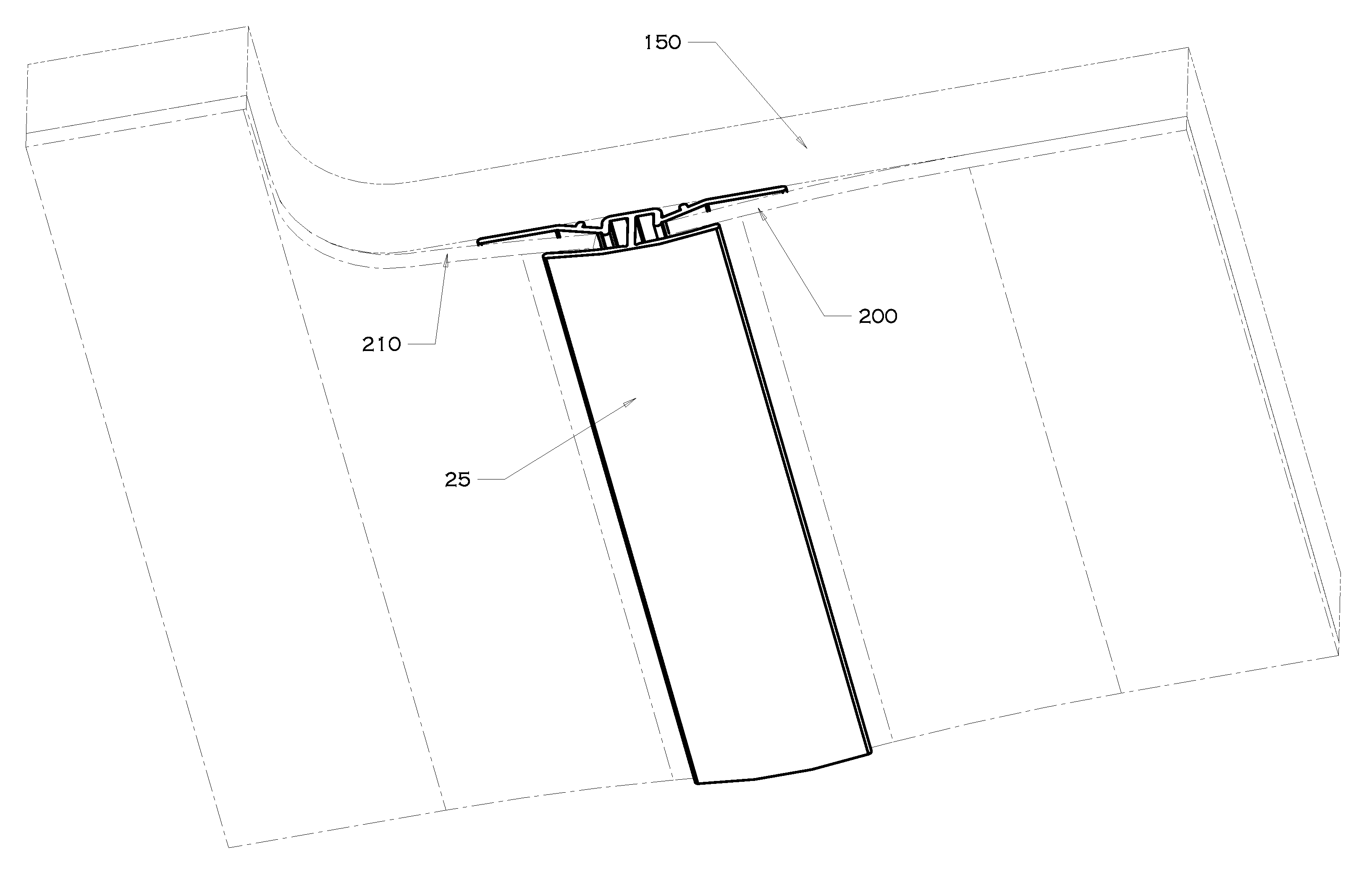
[0032]A current embodiment of the panel trim of the present invention is shown in FIGS. 3-8 and generally designated 25. The trim 25 can be used to capture the ends of adjacent panels 200, 210, and conceal the gap 213 between them (FIG. 8). In general, the trim 25 can include a cover 30, a base 40, a flange 52, and one or more flex regions 70. The cover, flange and base cooperate to define generally opposing channels 66 and 68. The flex region 70 allows for independent flexing or movement of the cover 30 to facilitate insertion of a first panel 200 into the first channel 66 (FIGS. 5-6), while maintaining the size of the second channel 68 so that a second panel 210 can be easily inserted into the second channel 68 (FIGS. 7-8).

[0033]The following terms will have the definitions presented. As used herein, “panel” refers to any material that forms a surface, including but not limited to composite, plastic (natural or fiber), or wood sheets, rolls, webs, boards...


PUM


Abstract

A panel trim including a cover and a base joined at opposite ends of a flange to form channels on opposite sides of the flange. The channels are adapted to receive panels, with the cover adapted to conceal the gap between the panels. The panel trim can include at least one ramp joined with the base. The panel trim can also include a flex region to enable independent flexing of opposite sides of the cover as panels are inserted into respective channels. The panel trim can be modified to accommodate linearly aligned panels, as well as panels that are at an angle to one another.

Description

BACKGROUND OF THE INVENTION[0001]The present invention relates to panel systems, and more particularly, to panel trim that conceals a gap between adjacent panels.[0002]Panel systems are frequently used to aesthetically or functionally enhance existing structures, such as walls. Most panel systems include large panels that come in a variety of thicknesses, depending on the application. To install the panel systems, a user cuts or shapes the panels to a desired configuration or dimension. Sometimes, the panels come pre-cut so that the user need not further modify them. The user then joins the panels, usually one-by-one, with a wall via adhesives or fasteners until the wall is sufficiently covered with the panels to the user's satisfaction.[0003]Typically, the panels are joined with the wall in a side-by-side configuration so that the edge of one panel is adjacent or abutting the edge of another panel. This configuration usually produces a visible gap or void between the panels. In som...

Claims


Application Information

Patent Timeline
Patent Type & Authority Applications(United States)
IPC IPC(8): E04F13/07E04B2/88
CPCE04F19/061E04F19/065E04F19/062E04F19/063E04F19/064
Inventor MEULEMANS, MICHAEL J.
Owner ISO TRUDE
Why Eureka
Try Eureka