Hidden Wideband Antenna

a wideband antenna and hidden technology, applied in the direction of resonant antennas, radiating element structural forms, protective materials, etc., can solve the problems of compromising the quality of tv reception at the edges of both vhf and uhf bands, and prior art antennas are not particularly attractive accessories in modern home furnishing settings, so as to improve broadband characteristics

Active Publication Date: 2010-04-08
SADOWSKI BOGDAN +1
View PDF7 Cites 40 Cited by
  • Summary
  • Abstract
  • Description
  • Claims
  • Application Information

AI Technical Summary

Benefits of technology

[0006]Accordingly, it is an object of the present invention to provide low-cost wideband antenna capable of quality reception of all over-the-air TV channels, throughout the VHF and UHF bands, and having external appearance appropriate for, and in harmony...

Problems solved by technology

V-shaped dipole and loop antennas, made from thin conductors, do not have a particularly broadband characteristics, thus the quality of the TV receptions is compromised ...

Method used


Image

  • Hidden Wideband Antenna
  • Hidden Wideband Antenna
  • Hidden Wideband Antenna

Examples


Embodiment Construction

[0014]Preferred embodiments of the present invention will now be described in details, with reference to the accompanying drawings. This invention may, however, be embodied in many different forms and should not be construed as limited to the embodiments set forth herein. Rather, these embodiments are provided so that the disclosure will be thorough and complete, and will fully convey the scope of the invention to those skilled in the art.

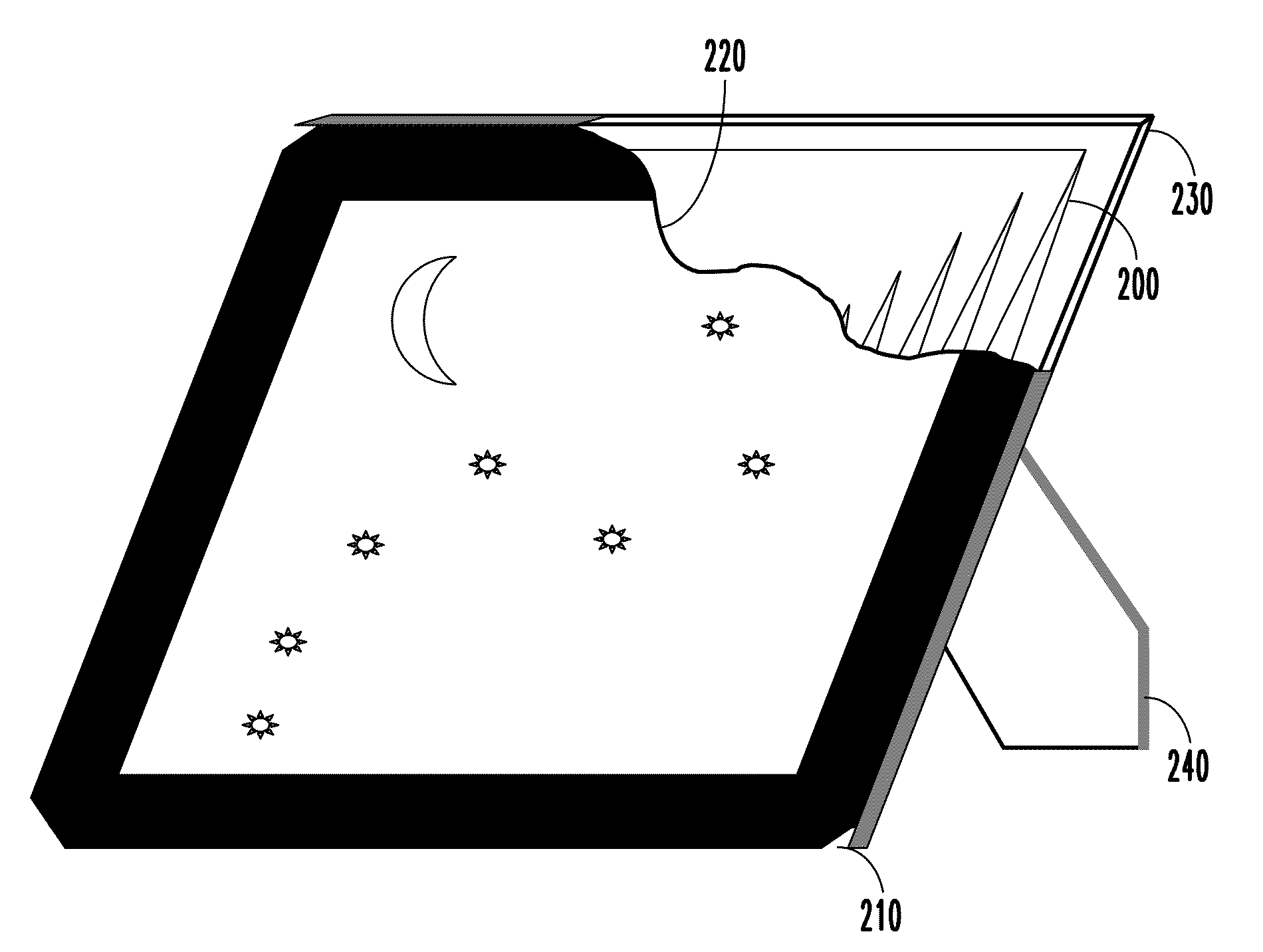
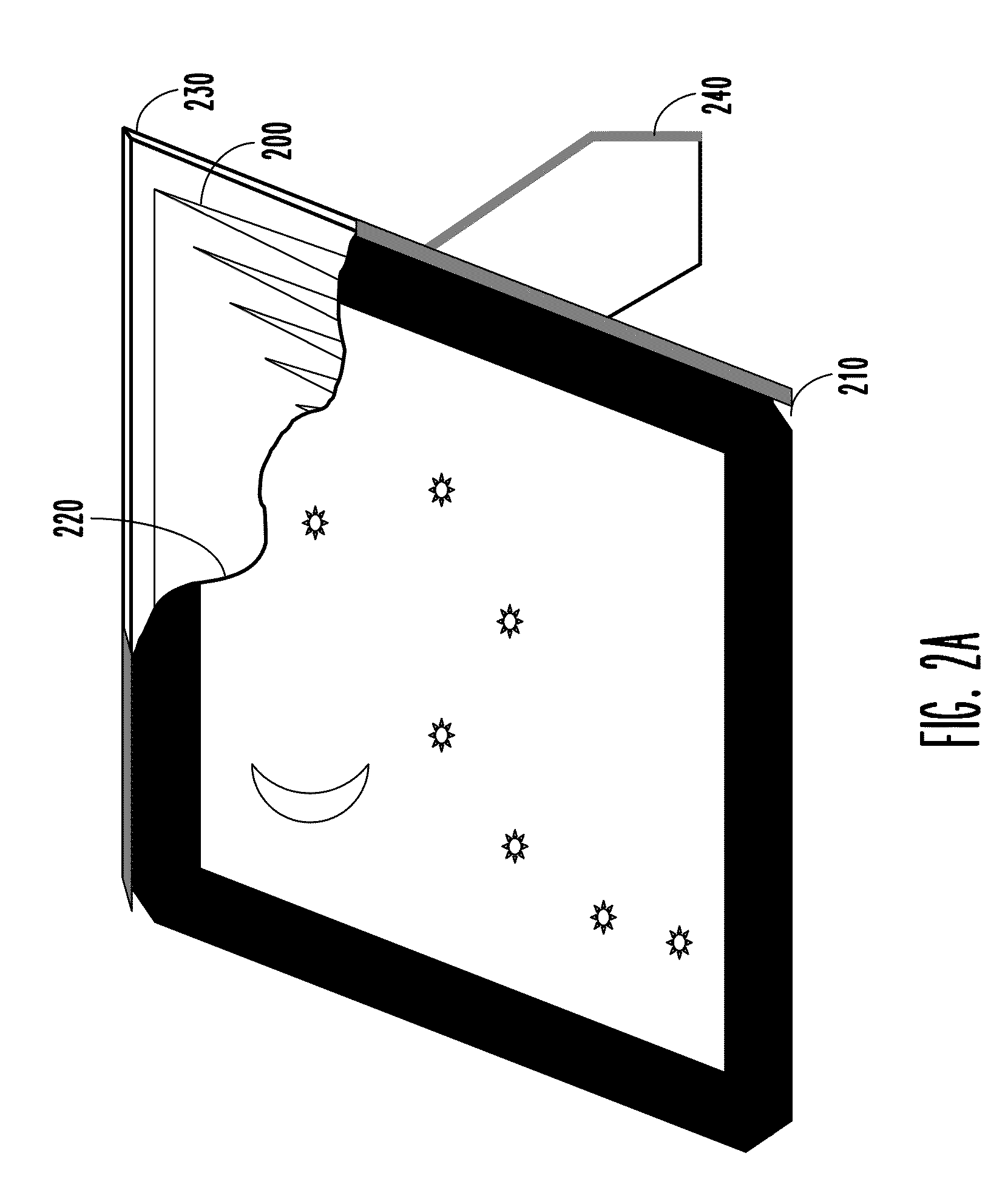
[0015]Referring now to FIG. 2A, FIG. 2B and FIG. 2C, hidden wideband antenna, according to the present invention, includes a wideband antenna 200. Wideband antenna 200 is attached to a back cover 230. Gluing is the preferred method of attachment, however other attachment methods are considered being within the scope of the invention. A support leg 240 is joined to the back cover 230 by a hinge mechanism 250. A picture 220 is inserted inside a frame 210. Picture 220 may include protective material covering its front, such as thin glass or transparen...


PUM


Abstract

A low-cost compact wideband antenna (200) has two triangular-shaped arms (500 and 510) formed by winding the conductive wire into a zigzag pattern. The two arms (500 and 510) form a compact bow-tie type antenna having equivalent electrical size larger then its mechanical dimensions. Two straight wires (530 and 540) are joined to, and electrically connected between two respective largest segment ends of two zigzag structures. The compact wideband antenna (200) is hidden inside the decorative household item (210) to provide antenna having external appearance appropriate for modern home furnishing setting with improved broadband characteristic across VHF and UHF bands but without the inconvenience of the large size.

Description

FIELD OF THE INVENTION[0001]This invention relates to electronic circuits, and more particularly to antennas and TV receivers.BACKGROUND OF THE INVENTION[0002]Wideband antennas are widely used in variety of applications including TV broadcast, radar, radio astronomy and radio-communications. Indoor antenna for TV broadcast reception is required to cover particularly broad range of frequencies across VHF and UHF bands. Heretofore, separate antennas were used to receive VHF and UHF bands. Output signals from both antennas were combined together into a single-connector output.[0003]FIG. 1 is a perspective view of such prior art antenna. Referring now to FIG. 1, a prior art indoor TV antenna assembly includes a V-shaped dipole antenna for VHF reception, comprising of two long arms 100 and 110, and a loop antenna 120, of round or rectangular shape, for UHF band reception. Both antennas are joined to a decorative base 130, made of insulator material. The base 130 also serves as an enclosu...

Claims


Application Information

Patent Timeline
IPC IPC(8): H01Q9/16H01Q1/42
CPCH01Q1/40H01Q9/28H01Q9/16
Inventor SADOWSKI, BOGDANSADOWSKA, ZOFIA
Owner SADOWSKI BOGDAN
Why Eureka
Try Eureka