Planar reflective array antenna

A planar reflectarray and antenna technology, which is applied to antennas, electrical components, waveguide horns, etc., can solve the problems of insufficient stability of the microstrip dielectric layer structure, lower gain, and influence on phase compensation, so as to improve the environmental adaptability of the antenna and reduce the Influence of element coupling and effect of canceling the influence of antenna performance

Active Publication Date: 2019-04-16
尚光林
View PDF9 Cites 2 Cited by
  • Summary
  • Abstract
  • Description
  • Claims
  • Application Information

AI Technical Summary

Problems solved by technology

[0003] The traditional planar reflectarray antenna is also called the microstrip reflectarray antenna. The microstrip reflectarray antenna adopts the microstrip structure. The microstrip dielectric layer as the unit support structure has many adverse effects on the performance of the reflectarray antenna. The dielectric layer increases the loss and reduces the gain
The second is that the microstrip dielectric layer is difficult to maintain flatness when working in an outdoor environment
The dielectric material is hygroscopic, absorbing air moisture under outdoor environmental conditions causes the dielectric layer to expand and shrink, resulting in warping of the dielectric layer and affecting the flatness of the reflective surface
The third is that the dielectric constant of the microstrip dielectric layer will change after moisture absorption, which will affect the phase compensation
Fourth, the structural stability of the microstrip dielectric layer is insufficient, and it is easy to be broken and damaged
[0005] The disadvantages of the above schemes are: as is known to researchers in this field, the reflectarray unit can achieve phase change by changing the size and length of the branches. In principle, the array unit requires a phase change of more than 360 degrees. Only when 360 degrees is satisfied can the phase angle be adjusted. Achieve comprehensive compensation, so that the reflectarray antenna achieves wide frequency band and good gain characteristics
The paper focuses on the description of the two structures, citing the data of the paper, and the basic scheme (such as Figure 11 shown) can achieve a phase change of 257 degrees, the preferred solution (such as Figure 12 shown) to achieve a phase change of 300 degrees, neither of which can achieve a 360-degree phase compensation
Limited by the phase compensation capability, the working frequency band is about 8.3%, and the antenna efficiency is not high

Method used


Image

  • Planar reflective array antenna
  • Planar reflective array antenna
  • Planar reflective array antenna

Examples


Embodiment 1

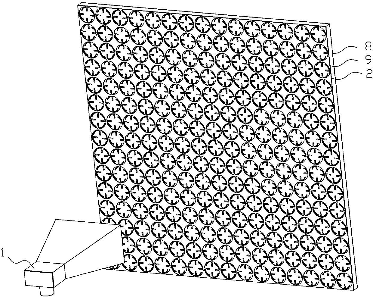
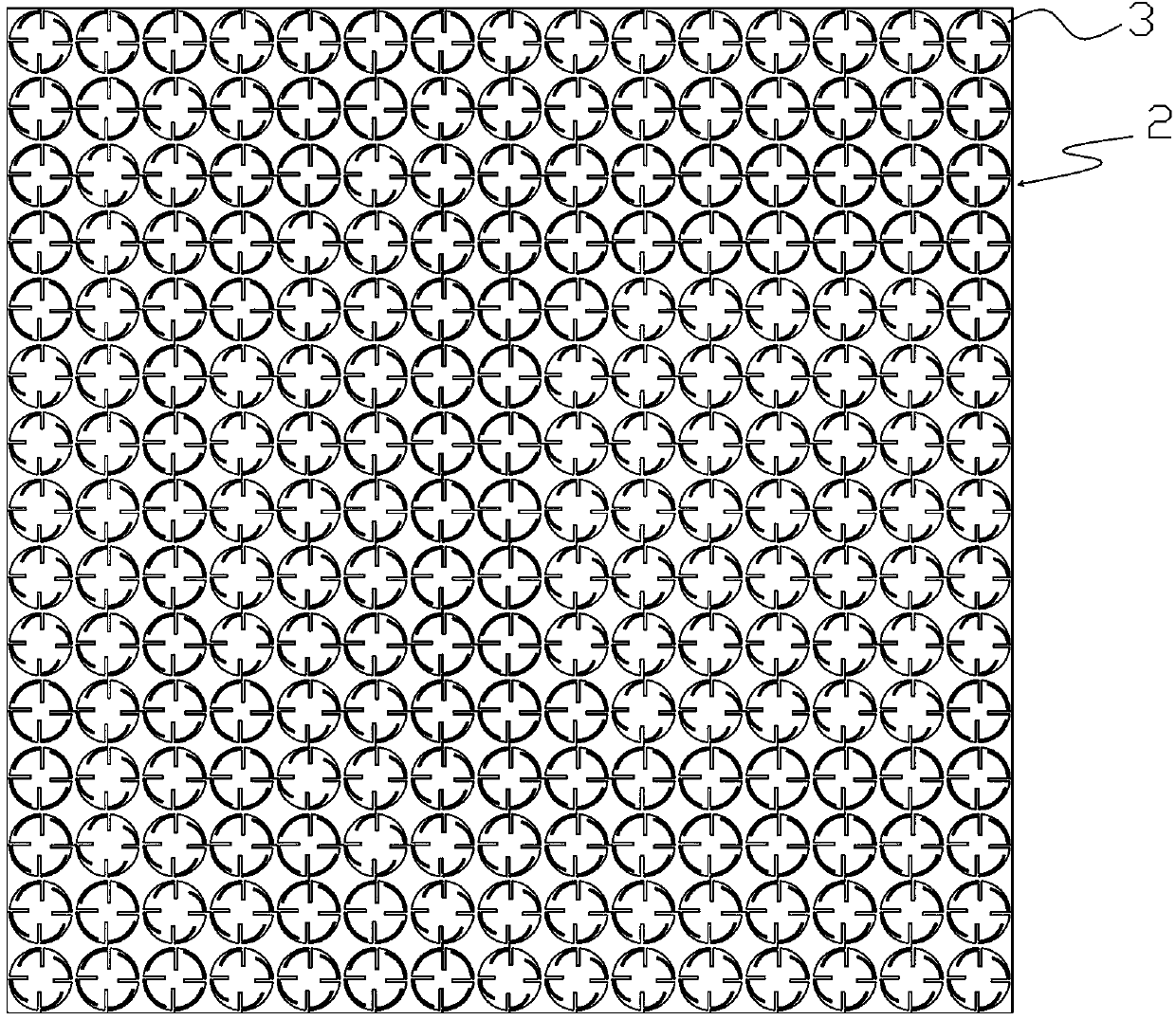
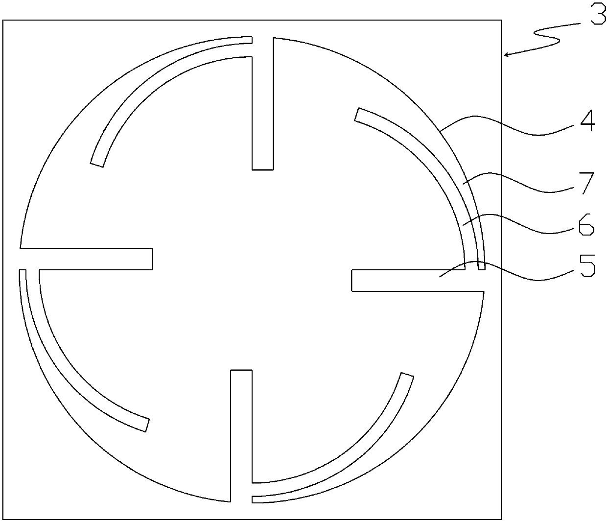
[0038] refer to Figure 1 to Figure 4 As shown, the planar reflectarray antenna of the present invention includes a feed 1 and a conductive planar reflectarray 2 . The feed 1 is used for transmitting or receiving electromagnetic waves. The conductive planar reflection front 2 is preferably square, but it is not limited thereto. It is used to scatter the electromagnetic wave emitted by the feed source 1 into a plane wave, or receive the plane wave and converge it to the feed source, or it can be applied to any need Applications where electromagnetic waves gather. Several identical reflective units 3 are distributed in an array on the conductive flat reflective front 2 . The reflection unit 3 includes a phase hole 4 and four branches distributed on the phase hole 4 , and adjacent reflection units 3 share a frame. A branch 6 with the same direction extends from one side of the branch 5 , and the branch 6 extends along the direction close to the edge of the phase hole 4 , formi...

Embodiment 2

[0053] refer to Figure 5 to Figure 6 As shown, in the planar reflectarray antenna of the present invention, on the basis of Embodiment 1, another preferred solution of the phase hole 4 of the reflective unit 3 is square. The branches 5 are distributed on or near the included angle of the phase hole 4 , and the branches 5 are preferably evenly distributed on the phase hole 4 in a non-centrosymmetric manner. The branches 6 are linear, and when the phase is adjusted, the branches 5 extend toward the center of the phase hole 4, and the branches 6 extend along the edge of the phase hole 4, wherein the branches 6 are far from the edge of the phase hole 4 The smallest part of the gap is less than one-tenth of the working wavelength. The effect similar to the circular structure can also be achieved through the above scheme. Note that the central direction of the square phase hole 4 is its diagonal intersection position, and the non-centrosymmetric distribution of branches means tha...

Embodiment 3

[0055] refer to Figure 7 As shown, in the planar reflectarray antenna of the present invention, on the basis of Embodiment 2, the branch 6 can extend from the phase hole 4 and extend along the direction of the phase hole 4, and its starting end is close to the Branches 5. Effects similar to those of Embodiment 1 and Embodiment 2 can also be achieved through the above scheme.


PUM


Abstract

The invention discloses a broadband planar reflective array antenna with a wider phase compensation range. The technical scheme adopted is as follows: the planar reflective array antenna includes a feed source and a conductive planar reflective array surface; the feed source is used for emitting or receiving electromagnetic waves; the conductive planar reflective array surface is used for scattering the electromagnetic waves emitted by the feed source into planar waves or receiving the planar waves and converging the planar waves onto the feed source; and a number of reflection units are distributed in an array on the conductive planar reflective array surface, and each reflection unit includes a phase hole and four branches distributed on the phase hole. The planar reflective array antenna is characterized in that twigs extend in the same direction from one side of the branches, the twigs extend near the edges of the phase holes, and slots for are formed between the twigs and the edges of the phase holes to adjust and control phase compensation and working frequency.

Description

technical field [0001] The invention relates to a planar reflection array antenna. Background technique [0002] With the development of communication technology, high-gain antennas are used more and more widely, especially in applications such as radar and satellite communication. As a new high-gain antenna, the planar reflectarray antenna has the advantages of light weight, small size, low cost, easy manufacture, easy assembly, and easy integration compared with the parabolic antenna; compared with the microstrip array antenna, it overcomes the The problem of large feed transmission loss. Therefore, it has become a research hotspot in the field of antennas since its birth, and it is one of the main research directions for large-scale high-gain antennas in the future. [0003] The traditional planar reflectarray antenna is also called the microstrip reflectarray antenna. The microstrip reflectarray antenna adopts the microstrip structure. The microstrip dielectric layer a...

Claims


Application Information

Patent Timeline
Patent Type & Authority Applications(China)
IPC IPC(8): H01Q13/02H01Q15/14H01Q19/10
CPCH01Q13/02H01Q15/145H01Q19/104
Inventor 尚济勇
Owner 尚光林
Why Eureka
Try Eureka