
Ball Joint and Sealing Collar for Such a Ball Joint

a sealing collar and ball joint technology, applied in the direction of shafts, bearings, couplings, etc., can solve the problems of restricting the options of ball joints to move, ball joints being very quickly worn out, and being damaged by joint movements, so as to prevent wear and tear, protect against corrosion, and ensure the effect of function

Inactive Publication Date: 2010-04-08
BERNHARDT PETER +1
View PDF15 Cites 5 Cited by
  • Summary
  • Abstract
  • Description
  • Claims
  • Application Information

AI Technical Summary

Benefits of technology

The present patent describes various embodiments of a ball joint with a sealing collar that ensures a safe function even in the case of a failure of the sealing collar. The sealing collar has an additional sealing section that prevents liquid and particles from entering the space between the ball head and the housing. The sealing collar can be attached to the housing or the ball stud using a clamping ring or a claw ring, and a separate grease can be used for each embodiment. The additional sealing section is integrally formed with the sealing collar and has a undulating shape to increase its flexibility and support. These features make the ball joint safer and more reliable, and prevent wear and tear.

Problems solved by technology

Therefore, a sealing collar must, on the one hand, sealingly and reliably be attached to the joint housing and to the pivot pin, on the other hand, however, it must not restrict the options of the ball joint to move, or be damaged by movements of the joint.
The disadvantage of known vehicle ball joints including a sealing collar is that in the case of a leakage—and the penetration of liquid or particles associated therewith—or in the case of a destruction of the sealing collar, these ball joints very rapidly wear out.

Method used


Image

  • Ball Joint and Sealing Collar for Such a Ball Joint
  • Ball Joint and Sealing Collar for Such a Ball Joint
  • Ball Joint and Sealing Collar for Such a Ball Joint

Examples


Embodiment Construction

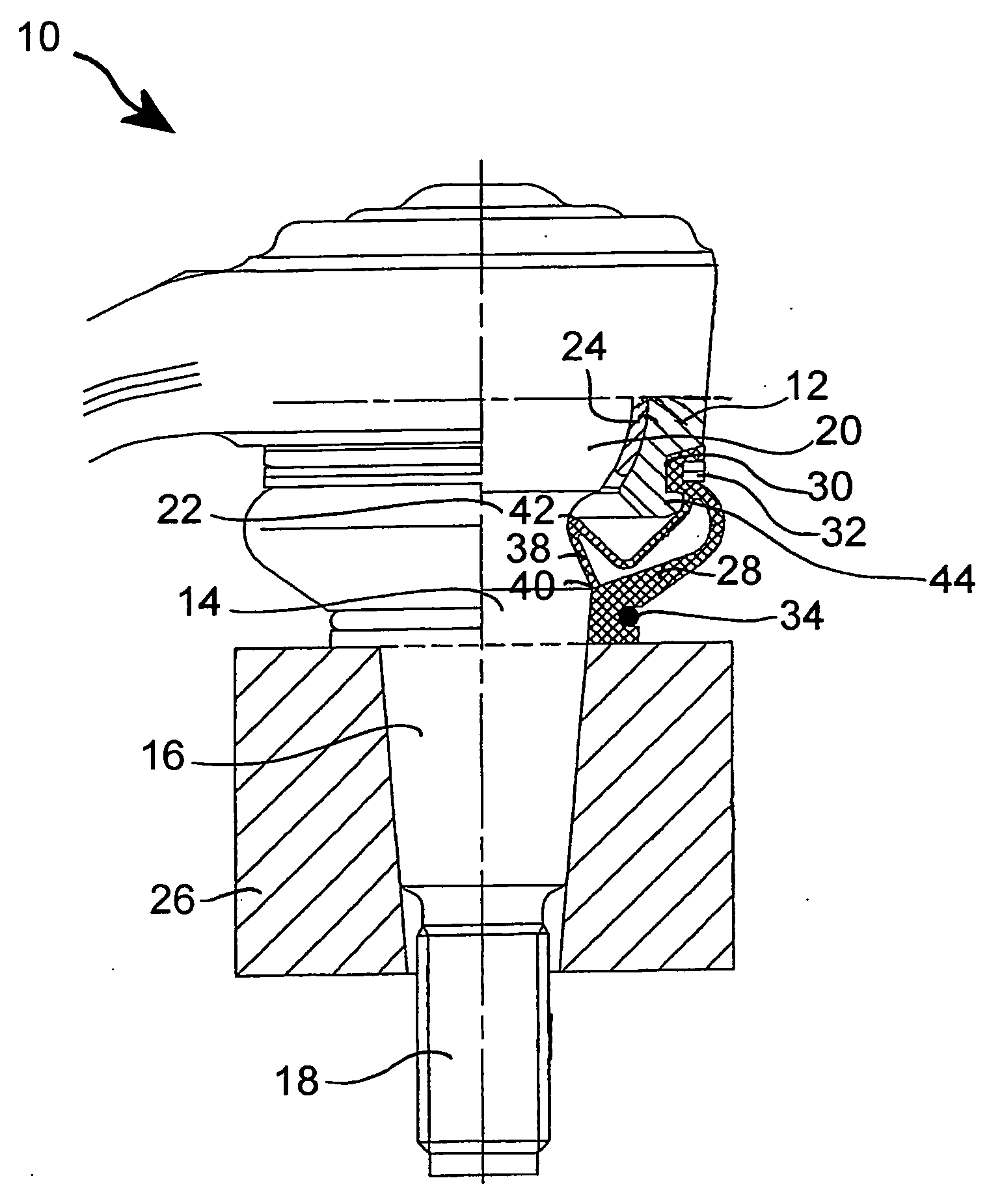
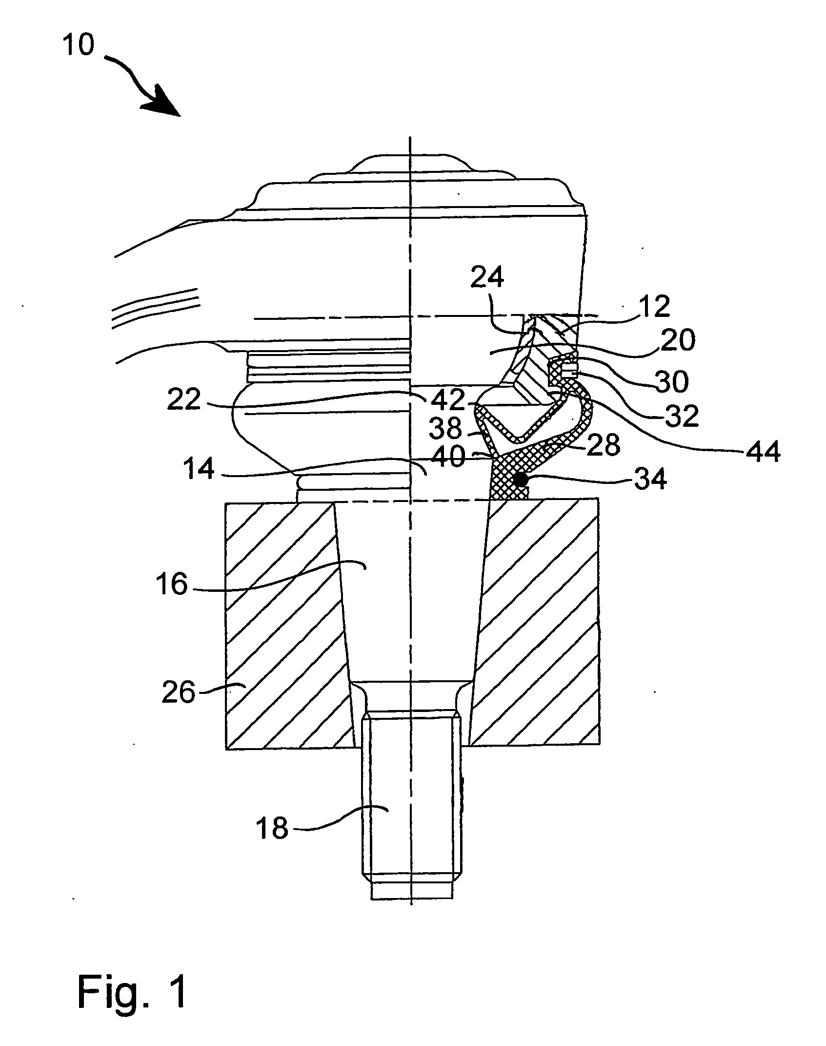
[0030]The ball joint 10 represented in FIG. 1 comprises as the essential components a housing 12 and a ball stud 14. The ball stud 14 includes a connecting bolt 16 which is adjoined by a thread 18 (schematically shown). A ball head 20 which is connected to the ball stud 14 via a ball neck 22 is received in a bowl 24 which in turn is fixed in the housing 12.

[0031]The ball joint 10 is attached to a component 26 which may, for example, be a part of a chassis for a motor vehicle. The ball stud 14 is inserted by its connecting bolt 16 and the thread 18 through the component 26 and may be attached to the latter by means of a nut (not shown).

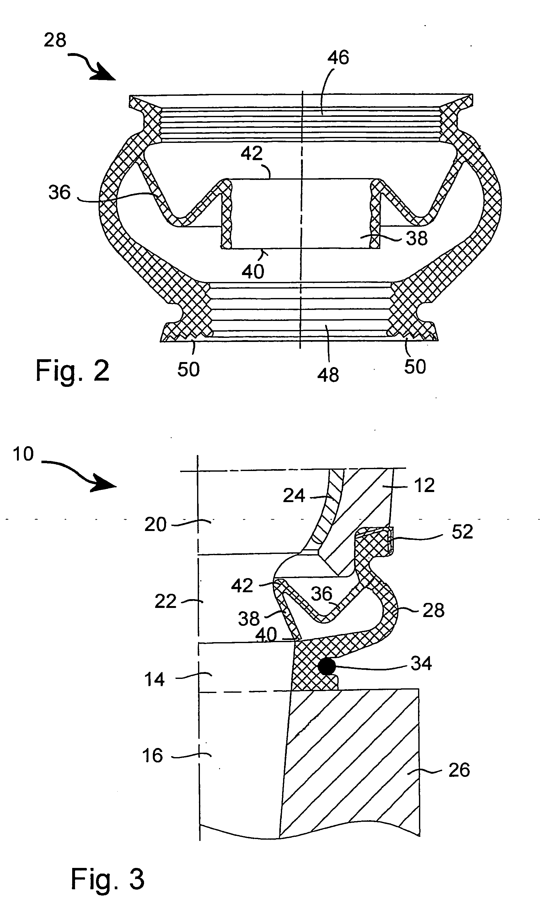
[0032]A sealing collar 28 consists of an elastic material having sealing properties, and its upper side according to the representation in the figure is attached to the housing 12. For this purpose, the upper end of the sealing collar 28 is placed in a surrounding housing groove 30 and urged against the housing 12 by means of a clamping ring 32. At its...


PUM


Abstract

A ball joint includes a housing, a ball stud, a ball head, and a sealing collar which rests against the housing and the ball stud, in order to seal between the same, the sealing collar having an additional sealing section that is integrally formed therewith and additionally seals between the housing and the ball head.

Description

CROSS-REFERENCE TO RELATED APPLICATIONS[0001]This application is a National Stage of International Application No. PCT / EP2006 / 006738 filed Jul. 10, 2006, which claimed priority to German Patent Application No. 20 2005 011 802.8 filed Jul. 27, 2005, the disclosures of both are incorporated herein by reference,BACKGROUND[0002]Various embodiments of a ball join are described herein. In particular, the embodiments described herein relate to a ball joint and a sealing collar for such a ball joint.[0003]Ball joints are known from the prior art and are used in a large variety of embodiments. In particular in the construction of motor vehicles, substantially all the ball joints have to be protected by sealing collars against dirt and moisture. Therefore, a sealing collar must, on the one hand, sealingly and reliably be attached to the joint housing and to the pivot pin, on the other hand, however, it must not restrict the options of the ball joint to move, or be damaged by movements of the ...

Claims


Application Information

Patent Timeline
Patent Type & Authority Applications(United States)
IPC IPC(8): F16C11/00F16C11/06
CPCY10T403/32729F16C11/0671F16C11/068F16C2210/02
Inventor BERNHARDT, PETERMETTE, ULRICH
Owner BERNHARDT PETER
Learn More