System, method and apparatus for concentric tubing deployed, artificial lift allowing gas venting from below packers

a technology of concentric tubing and artificial lift, which is applied in the direction of drilling casings, drilling pipes, borehole/well accessories, etc., can solve the problems of reducing the efficiency of the artificial lift system, exposing the artificial lift system to potential gas lockage, and reducing the efficiency of the us

Inactive Publication Date: 2010-04-15
BAKER HUGHES INC
View PDF22 Cites 22 Cited by
  • Summary
  • Abstract
  • Description
  • Claims
  • Application Information

AI Technical Summary

Benefits of technology

[0007]Embodiments of a system, method, and apparatus for artificial lift deployed on concentric tubing that allows gas to be vented from below packers in a well are disclosed The system allows for the easy deployment of an artificial lift system (e.g., an electrical submersible pump, or ESP) with the added benefit of two concentric flow paths. A central flow path is used for the fluid prod...

Problems solved by technology

Venting gas in the annulus, however, results in an inventory of gas build up within the annulus that is typically not considered desirable or acceptable.
In well applications where dual strings, vented packers or some alternative solution cannot be used, the artificial lift system is exposed to potential gas lock when “free gas” levels at the pump intake are sufficiently high.
This pr...

Method used


Image

  • System, method and apparatus for concentric tubing deployed, artificial lift allowing gas venting from below packers
  • System, method and apparatus for concentric tubing deployed, artificial lift allowing gas venting from below packers
  • System, method and apparatus for concentric tubing deployed, artificial lift allowing gas venting from below packers

Examples


Embodiment Construction

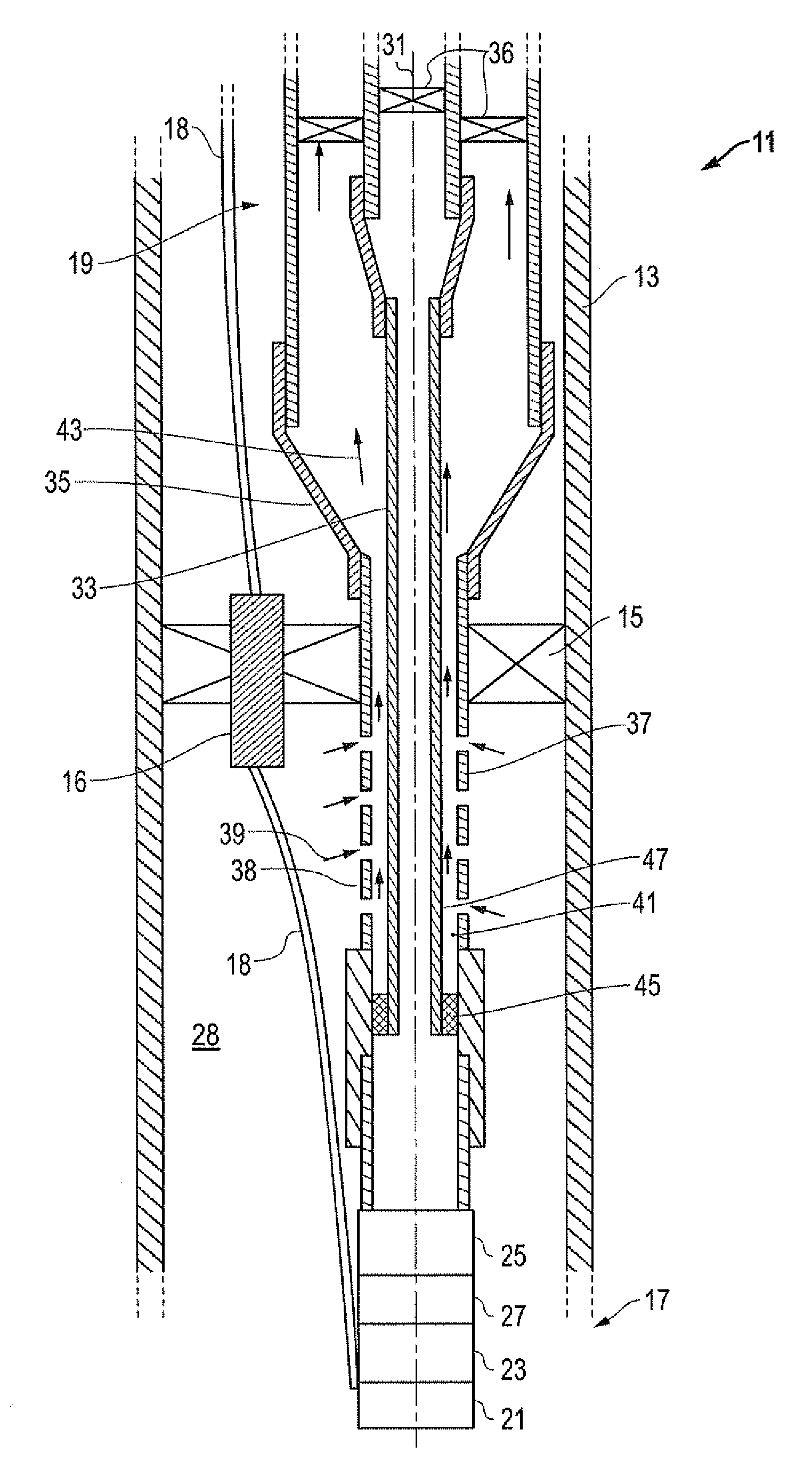
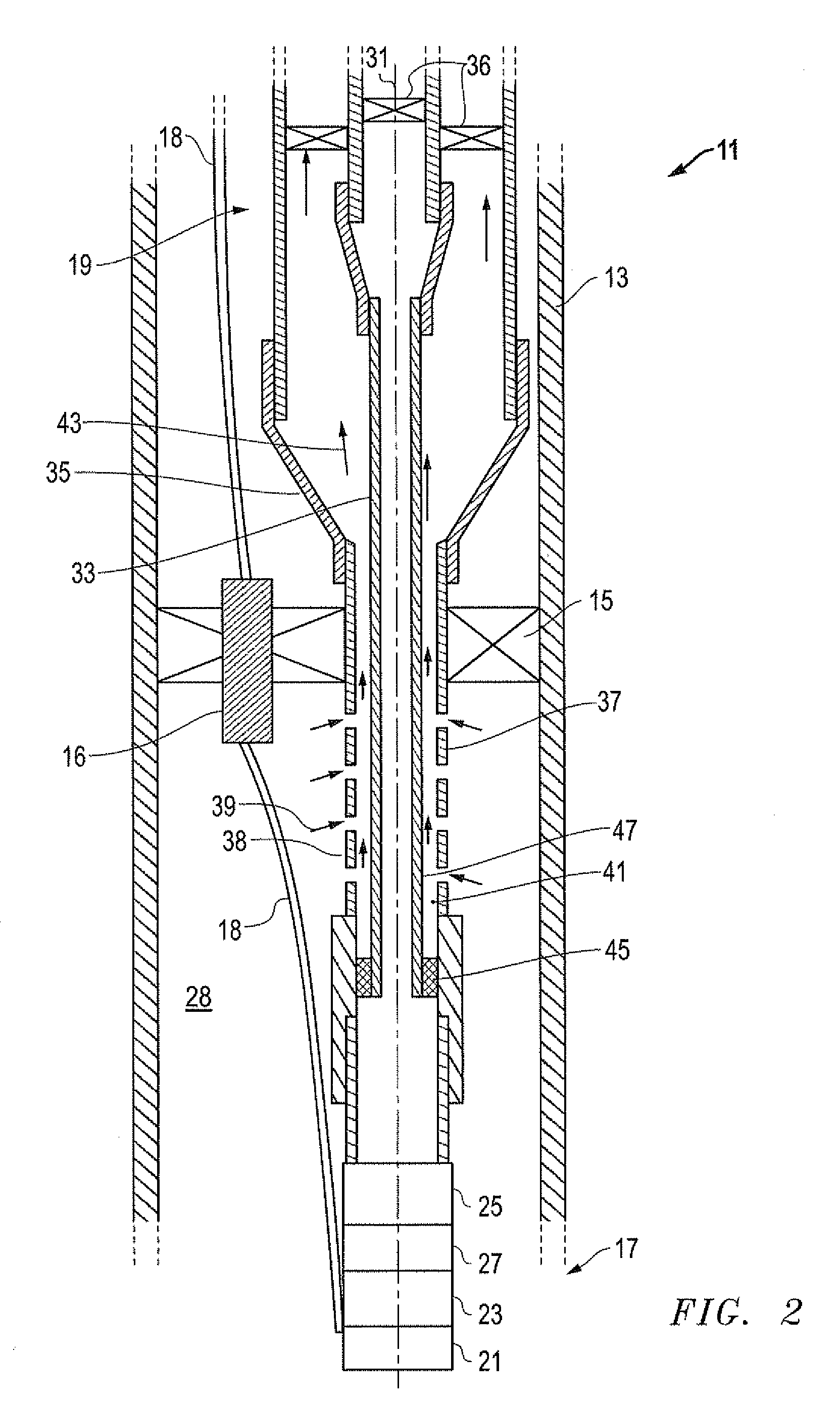
[0016]Referring to FIGS. 2-4, embodiments of a system, method and apparatus for an artificial lift deployed on concentric tubing that allows gas to be vented from below a packer in a well are illustrated. The invention permits the use of alternative gas separation techniques to provide more advantageous gas venting systems.

[0017]For example, in the well system of FIG. 2, the invention comprises a well 11 having casing 13 installed therein and a packer 15 mounted in the casing 13. An artificial lift, such as an electrical submersible pump (ESP) 17 (e.g., a centrifugal or progressive cavity pump), is mounted to a tubing string 19 that extends from a surface of the well 11. The artificial lift or ESP 17 is located below the packer 15. The ESP 17 may comprise a motor 21, seal section 23 and pump 25. The ESP 17 may further comprise a gas separator 27 for separating gas from the fluid and releasing gas into a casing annulus 28 between the casing 13 and tubing string 19 (e.g., a perforated...


PUM


Abstract

An artificial lift deployed on concentric tubing allows gas to be vented from below packers in a well. A central flow path is used for the fluid production from the artificial lift system, while an outer concentric tubing allows for the venting and production of gas from below a packer. The gas enters the outer concentric flow path through a perforated sub set that is located below the packer. Sealing of the inner concentric string flow from the outer concentric flow path is achieved with a polished bore receptacle and stinger assembly.

Description

BACKGROUND OF THE INVENTION[0001]1. Technical Field[0002]The present invention relates in general to artificial lift for oil and gas wells and, in particular, to an improved system method and apparatus for artificial lift deployed on concentric tubing that allows gas to be vented from below packers in an oil and gas well.[0003]2. Description of the Related Art[0004]In oil and gas wells, artificial lift systems (e.g., pumps) are used to extract the fluid from the wells. In some wells, the pumps are set in the casing below the packers where it is typical to only draw down the wells to no more than the “bubble point.” The bubble point is the pressure at which gas vapor first separates from a fluid. When the pressure remains above the bubble point, gas does not form below the packer and therefore eliminates the need to vent gas from below the packer. Another conventional design provides a vented packer that allows the gas to escape to the annulus between the casing and the production st...

Claims


Application Information

Patent Timeline
IPC IPC(8): E21B43/00E21B17/00E21B34/00
CPCE21B17/18E21B43/38E21B43/121E21B43/128
Inventor THOMPSON, DAVID
Owner BAKER HUGHES INC
Why Eureka
Try Eureka