Rail joint assembly using embedded load transfer keys and method therefor

a load transfer key and load transfer technology, applied in rail joints, roads, constructions, etc., can solve the problems of service reliability, service delay and additional costs incurred due to service delays and/or failures, and achieve the effect of strengthening the joint and minimizing the effects of environmental stress on the join

Inactive Publication Date: 2010-04-15
TRANSPORTATION TECH CENT
View PDF20 Cites 6 Cited by
  • Summary
  • Abstract
  • Description
  • Claims
  • Application Information

AI Technical Summary

Benefits of technology

[0012]A new rail joint assembly for joining the ends of two rails together at a joint is set forth that strengthens the joint against heavy railway loads and that minimizes the effects of environmental stresses on the joint. The new rail joint assembly includes a pair of joint bars with each joint bar having one side configured to the side of the web. Mechanical fasteners mount the joint bars to the web sides of the two rail ends so that the joint bars span across the joint. The configured sides of the joint bars are held against the opposing sides of the webs of the two rail ends. Pairs of load be

Problems solved by technology

A continued need exists to improve upon such joint designs because both mechanical and/or insulated joints have a lower service life than the rail itself.
Generally insulated joints are replaced five to ten times during the service life of the rail and the resulting cost to replace failed mechanical or insulated joints is expensive.
Additional costs are incurred due to service delays and service reliability.
Railway loads, especially heavy railway loads, cause adhesive failure, failure of the mechanical fasteners, and failure of the joint bar.
Insulated adhesive joints when subjected to such environmental stress and railway loads may lose strength.
Such premature failures may cause one or more of the mechanical fasteners to then undergo mechanical stress resulting i

Method used


Image

  • Rail joint assembly using embedded load transfer keys and method therefor
  • Rail joint assembly using embedded load transfer keys and method therefor
  • Rail joint assembly using embedded load transfer keys and method therefor

Examples


Embodiment Construction

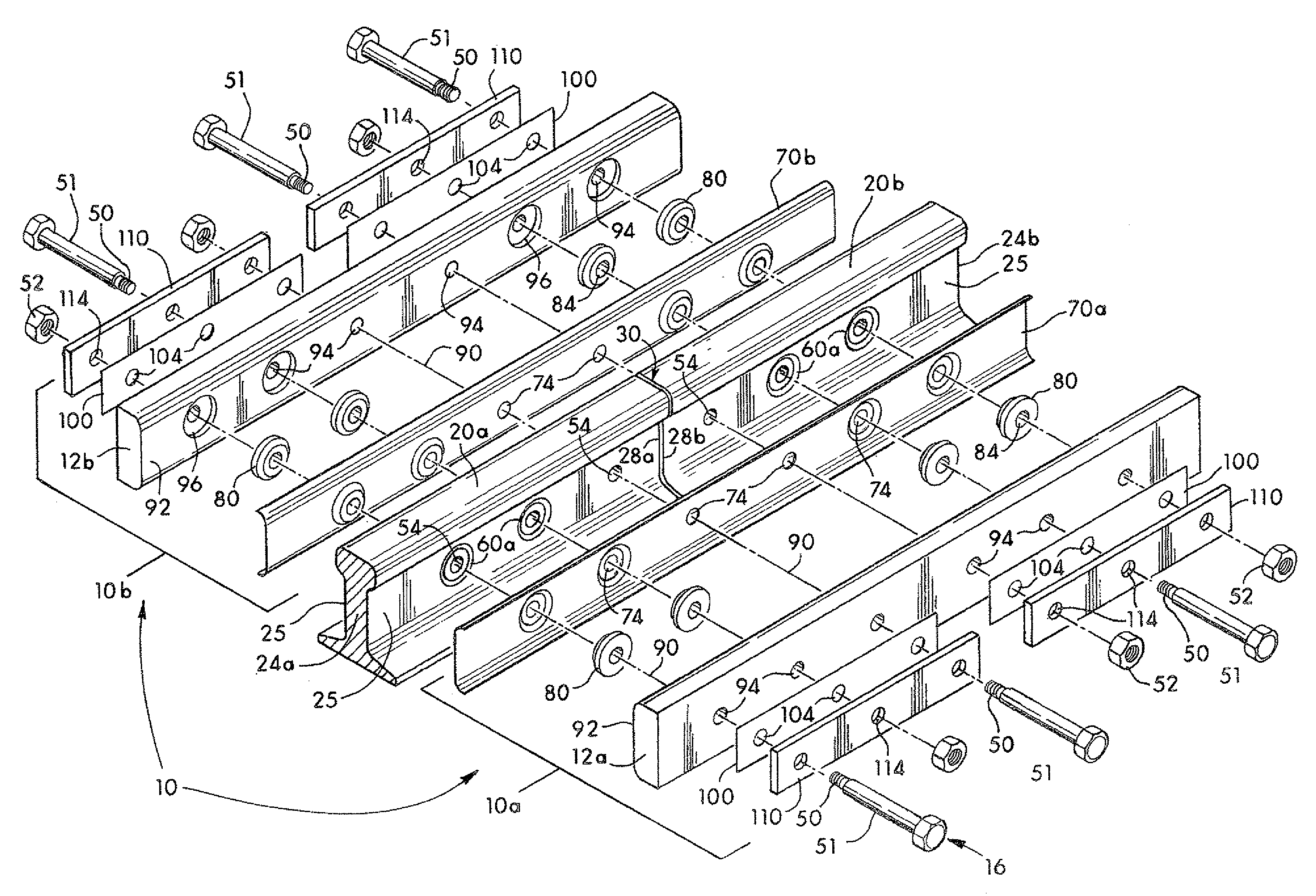
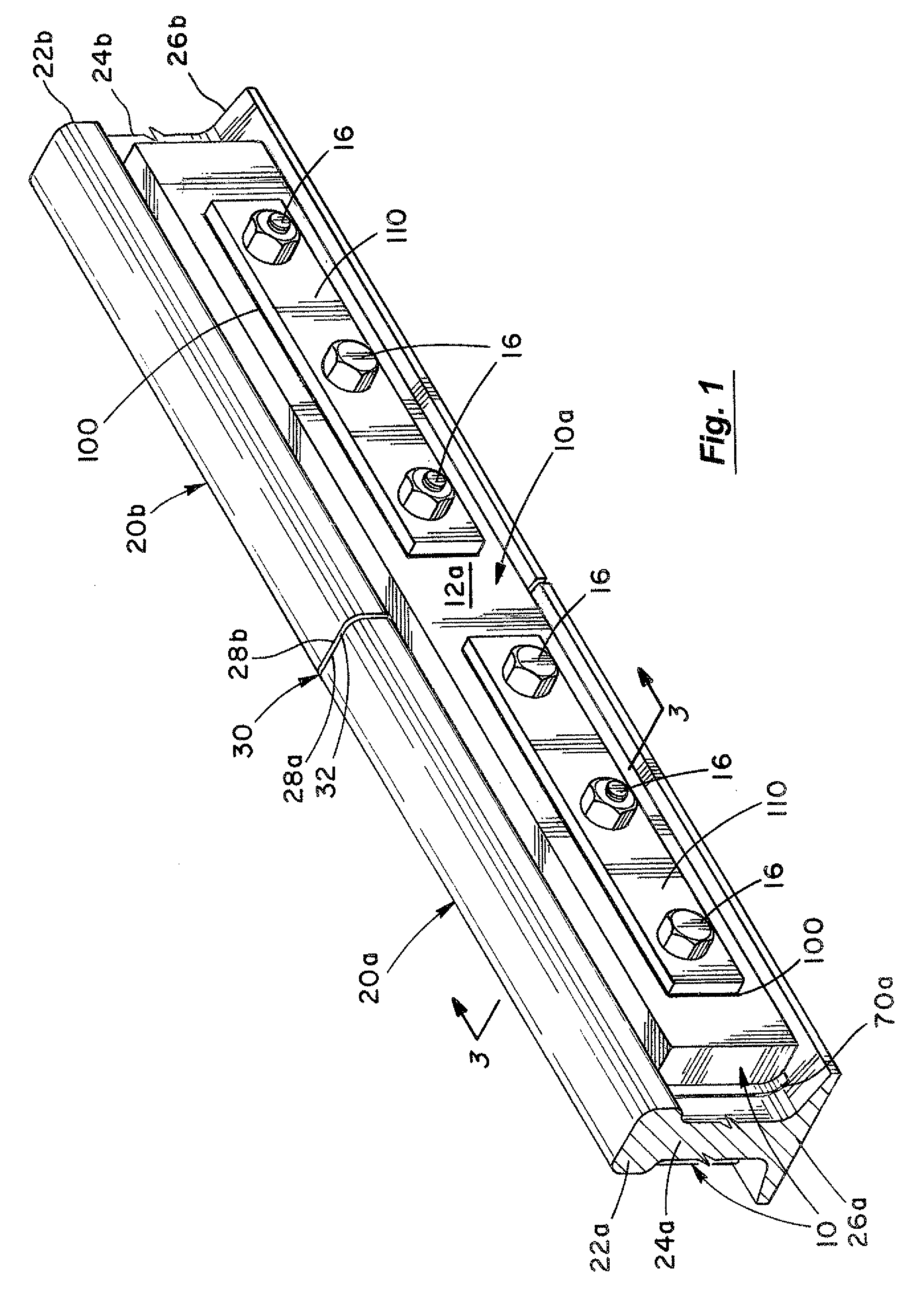
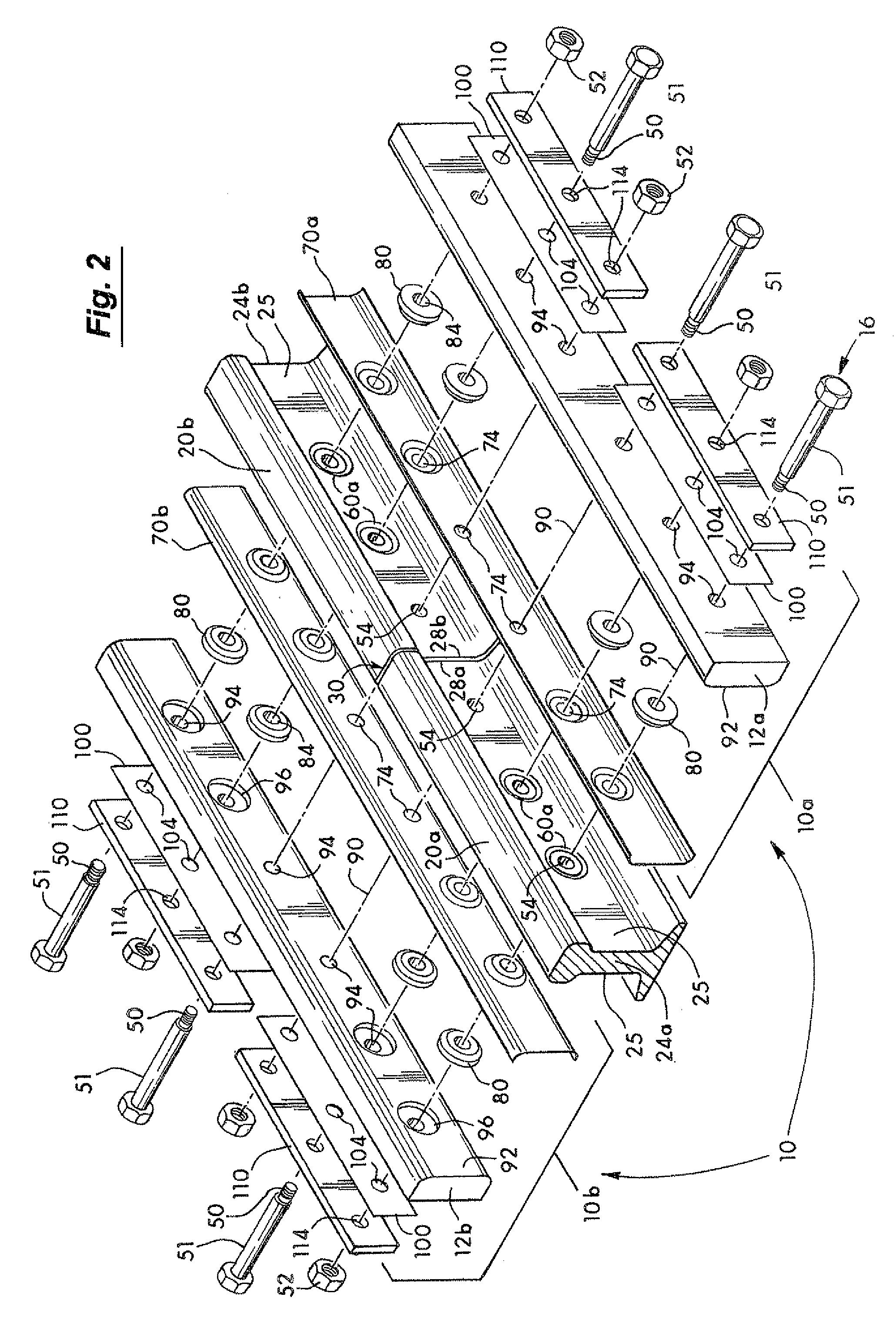
[0029]In FIG. 1, the rail joint assembly 10 of the invention is shown joining two rails 20a and 20b together at a joint 30. This occurs on conventional railroad track (not shown). The rail joint assembly 10 functions to transfer railway load forces on the two rails 20a and 20b from one rail to the next rail using components that both strengthen the rail joint and minimize component failure therein.

[0030]Each rail 20a and 20b has a head 22a and 22b, a web 24a and 24b, a base 26a and 26b, and an end 28a and 28b, respectively. The rails 20a and 20b are conventional and are of a thick web, regular web or any desired web construction. In the embodiment of FIG. 1, the rails 20a and 20b are identical and a thick web rail is illustrated. At joint 30, a conventional spacer 32 may be inserted between the two ends 28a and 28b. The spacer 32, in some applications, is an insulator to provide electrical isolation between the two ends 28a and 28b.

[0031]One side 10a of the rail joint assembly 10 i...


PUM


Abstract

A rail joint assembly joining the ends of two rails together includes a pair of joint bars. Each joint bar having one side configured to the rail web side. Mechanical fasteners mount the joint bars to the web sides. Pairs of load bearing keys are embedded in web counter bores at predetermined depths into the webs and embedded in adjacent joint bar counter bores at predetermined depths into the joint bars. The pairs of keys in the webs and the joint bars transfer railway loads through the joint and substantially strengthen the rail joint assembly.

Description

BACKGROUND OF THE INVENTION[0001]1. Field of the Invention[0002]The invention relates to a rail joint assembly for joining rail ends together on railroad track and, more particularly, to a rail joint assembly more efficiently transferring both vertical and longitudinal railway loads through a strengthened rail joint.[0003]2. Discussion of the Background[0004]Early on, railroad operators butted rail ends together and mechanically fastened the rail ends together at the joint with joint bars on each side of the rail held in place by bolts through the web of each rail end.[0005]A need arose to electrically isolate the rail ends from each other for train detection and for traffic control circuits that use the rail as conductors. Insulating adhesives such as epoxy have been used to both strengthen and to electrically isolate the two rail ends. U.S. Pat. No. 3,837,948 sets forth the use of both a thermoplastic adhesive layer which is itself normally electrically insulating to lock the rail...

Claims


Application Information

Patent Timeline
IPC IPC(8): E01B11/54E01B11/00
CPCE01B11/54
Inventor AKHTAR, MUHAMMAD NAEEMDAVIS, DAVID D.
Owner TRANSPORTATION TECH CENT
Why Eureka
Try Eureka