
Touch screen panel and fabrication method thereof

a technology of touch screen and fabrication method, which is applied in the direction of conductive layers on insulating supports, instruments, computing, etc., can solve the problems of capacitive touch screen elements that are not suitable for a relatively large screen, resistive touch screen elements that are not durable enough, and require an additional control system, so as to facilitate the appearance of information devices, save manufacturing costs of information devices, and cost-effective

Inactive Publication Date: 2010-04-15
SAMSUNG ELECTRONICS CO LTD
View PDF4 Cites 23 Cited by
  • Summary
  • Abstract
  • Description
  • Claims
  • Application Information

AI Technical Summary

Benefits of technology

[0014]Accordingly, the present invention has been made to provide a touch screen panel and a manufacturing method thereof which can diversify the appearance of the information apparatus.
[0023]According to an exemplary aspect of the present invention, the touch screen panel including the touch screen element is operated in a resistive scheme and also can be mounted on the curved window, so as to facilitate making the appearance of the information device to have diverse designs. Further, the touch screen panel preferably is manufactured using the resistive touch screen element, rather than using the capacitive touch screen element, so as to advantageously save the manufacturing cost of the information device and provide the user with a cost-effective information device.

Problems solved by technology

However, there is a disadvantage in that the resistive touch screen element does not have sufficient durability, is thick, and is not suitable for a relatively large screen.
However, there is a disadvantage in that the capacitive touch screen element requires an additional control system and its circuit is complex.
The conventional resistive touch screen element directly senses the press power of the user so that, as discussed previously, the element should be mounted on an exterior surface of the apparatus, i.e. the display device, and it is difficult to have a curved surface.
As a result, the resistive touch screen element has an advantage of easiness of the manufacture and low cost, but simultaneously has an disadvantage of difficulty of being formed in a curved surface, so as to cause a problem in diversifying the appearance of the information device.

Method used


Image

  • Touch screen panel and fabrication method thereof
  • Touch screen panel and fabrication method thereof
  • Touch screen panel and fabrication method thereof

Examples


Embodiment Construction

[0029]Hereinafter, exemplary embodiments of the present invention will be described with reference to the accompanying drawings. In the following description, detailed explanation of known related functions and constitutions may be omitted to avoid unnecessarily obscuring appreciation of the subject matter of the present invention by a person of ordinary skill in the art.

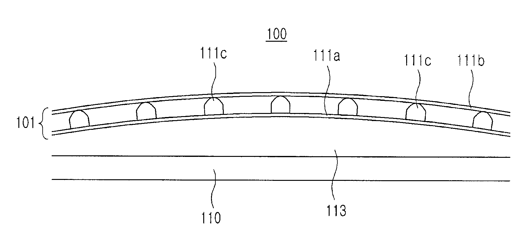
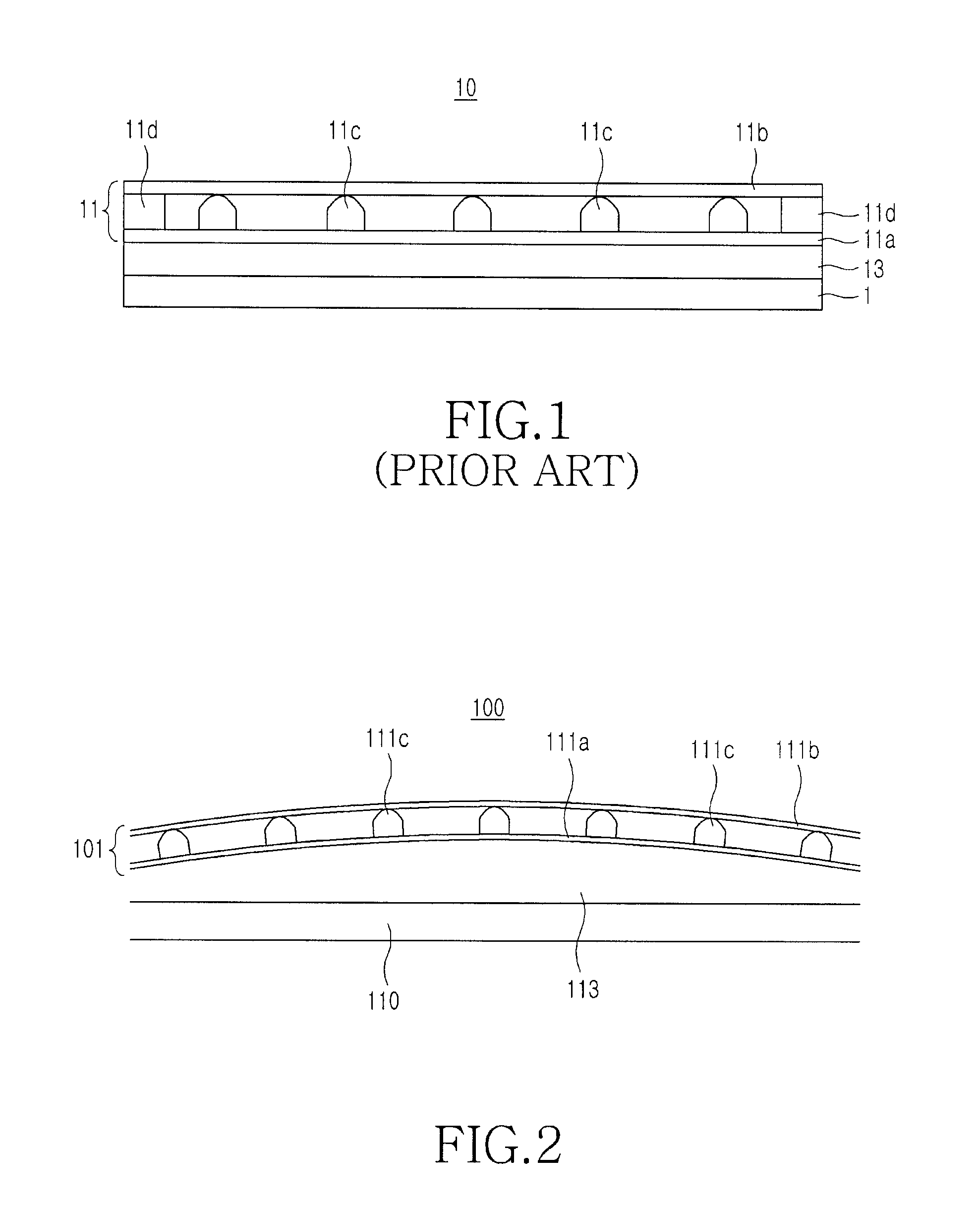
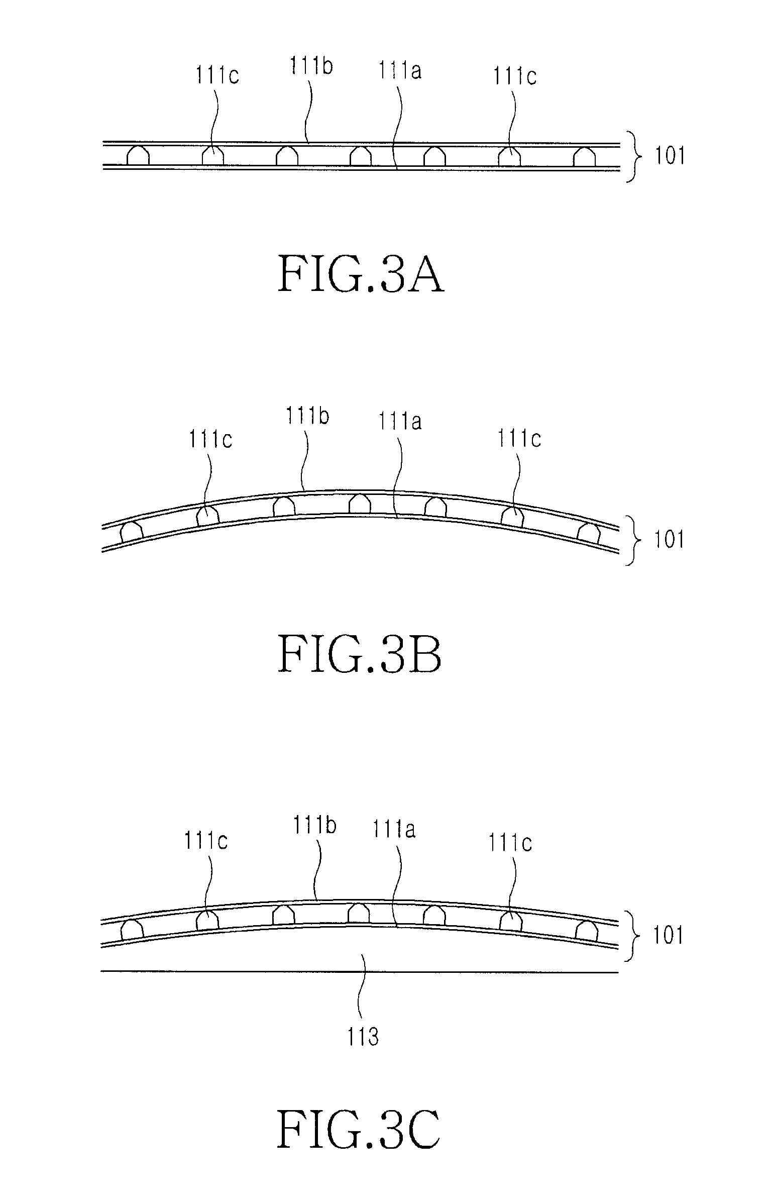
[0030]FIG. 2 is a sectional view illustrating the construction of a display device 100 having a touch screen panel according to an exemplary embodiment of the present invention. As shown in FIG. 2, the display device 100 preferably includes a display element 110 and a window 113 for protecting the display element 110. The touch screen panel includes the window 113 and a touch screen element 101 attached to an exterior-side surface of the window 113. The window 113 has one surface being curve-shaped and may be substantially transparent or translucent. If the window 113 is mounted on the display element 110, the curve...


PUM


Abstract

A touch screen panel includes a window having one curved surface and mounted on a front surface of a display element. A touch screen element is attached to the curved surface of the window, wherein the touch screen element is processed to have a curvature corresponding to a curvature of the curved surface of the window prior to being attached to the curved surface of the window. The touch screen panel operates in a resistive scheme and can be mounted on the window shaped like a curve. The invention makes it possible to manufacture the information device having various designs in accordance with consumer demands yet retaining a low cost.

Description

CLAIM OF PRIORITY [0001]This application claims priority under 35 U.S.C. §119(a) to a Korean Patent Application entitled “Touch Screen Panel and Fabrication Method thereof” filed in the Korean Intellectual Property Office on Oct. 14, 2008 and assigned Serial No. 10-2008-0100632, the contents of which are incorporated herein by reference in its entirety.BACKGROUND OF THE INVENTION[0002]1. Field of the Invention[0003]The present invention relates to a display device, and more particularly to a touch screen panel that is mounted on a display device so as to provide an input function.[0004]2. Description of the Related Art[0005]Conventionally, information apparatuses (devices), such as a cellular phones, navigation apparatuses for vehicles, and a portable multimedia reproducing devices, are output devices that typically include a speakerphone and a display device. Further, such information apparatuses are input devices for voice calls, permitting character input, retrieving stored infor...

Claims


Application Information

Patent Timeline
IPC IPC(8): G06F3/045G06F3/041H05K13/00
CPCG06F3/041Y10T29/49002G06F3/045G06F3/0412G06F2203/04103H01B5/14
Inventor PARK, JAE-YONGJI, YOUNG-BAE
Owner SAMSUNG ELECTRONICS CO LTD
Learn More