
Optical transmission coupling

Active Publication Date: 2010-04-15
FUJIFILM SONOSITE
View PDF49 Cites 7 Cited by
  • Summary
  • Abstract
  • Description
  • Claims
  • Application Information

AI Technical Summary

Benefits of technology

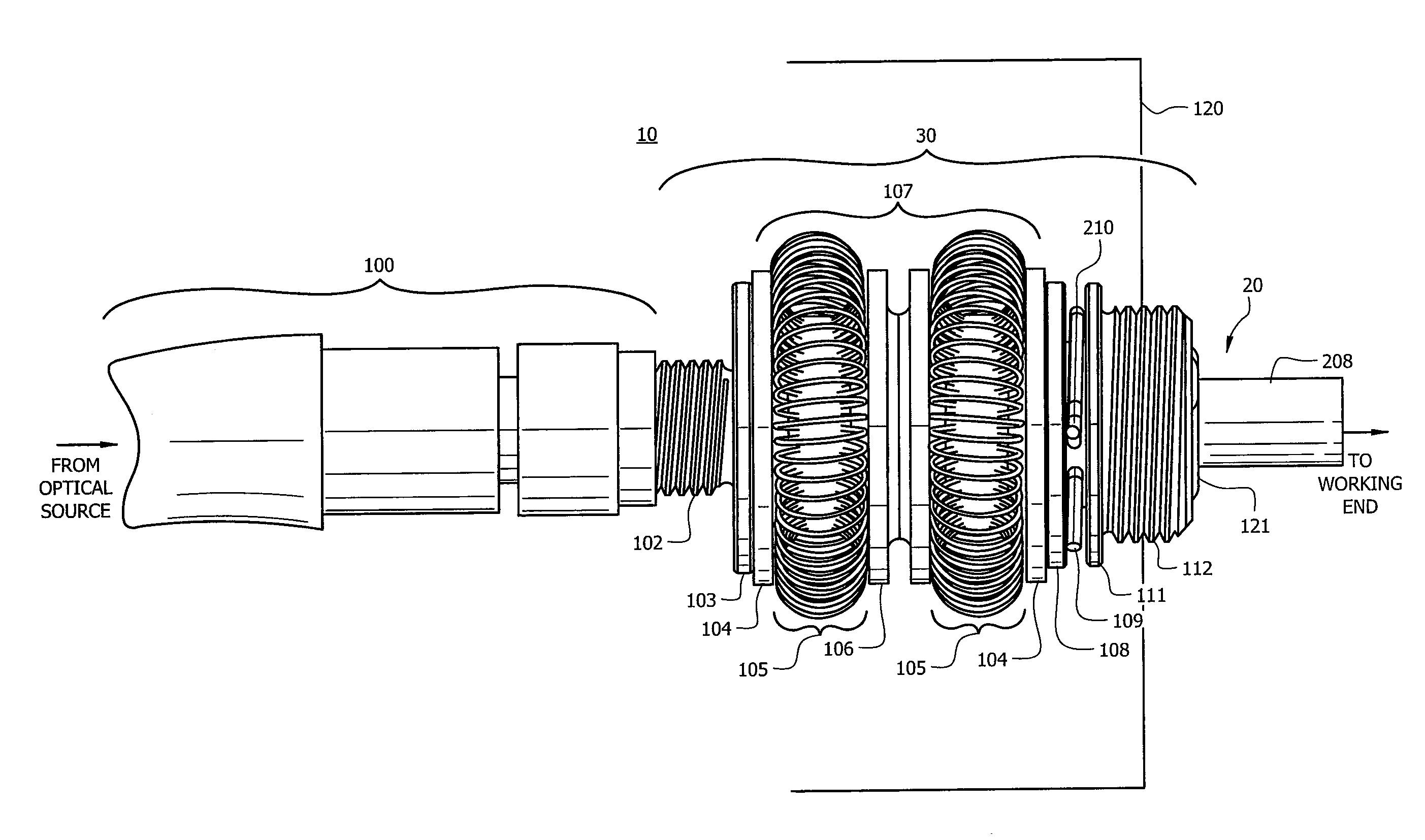
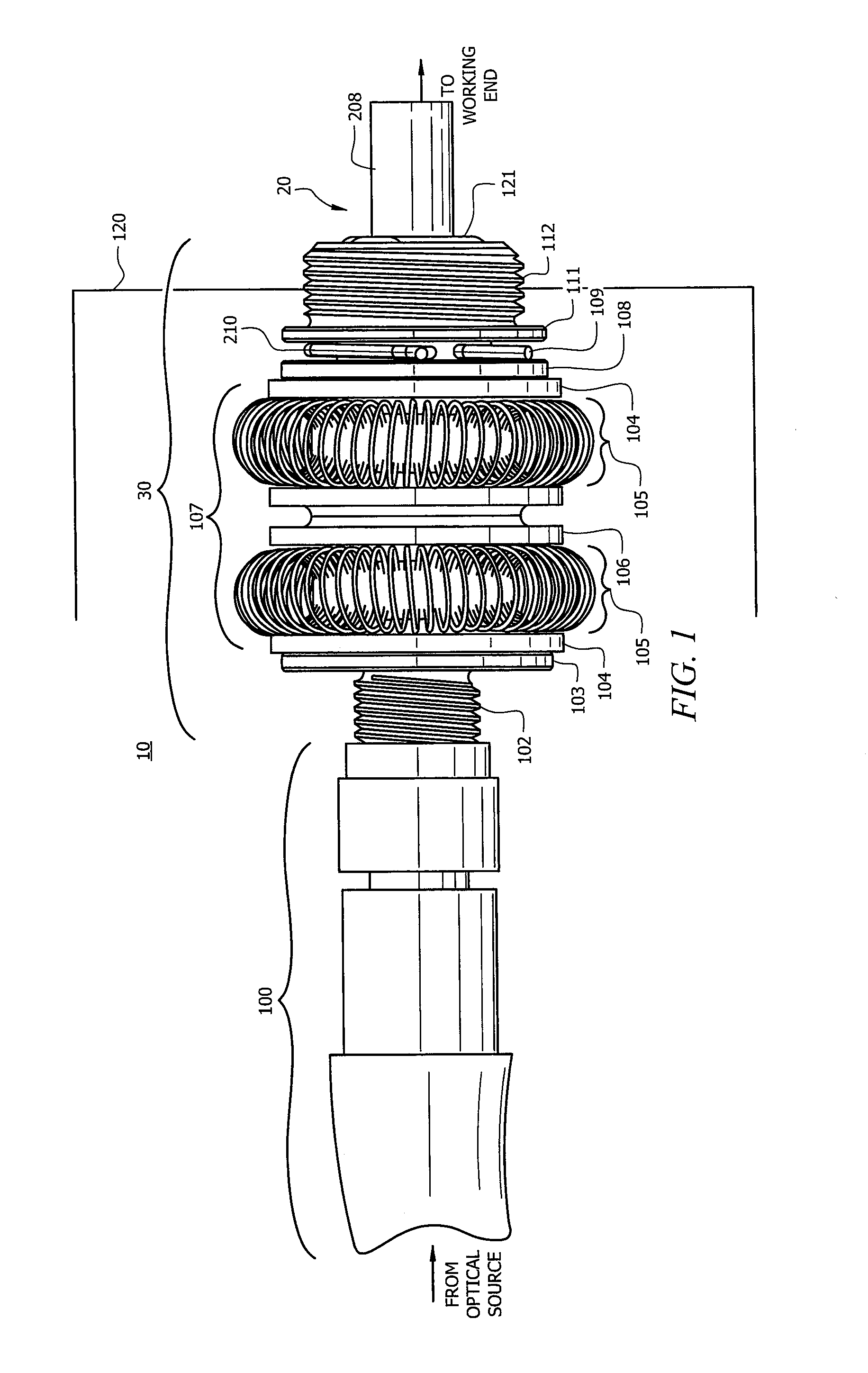
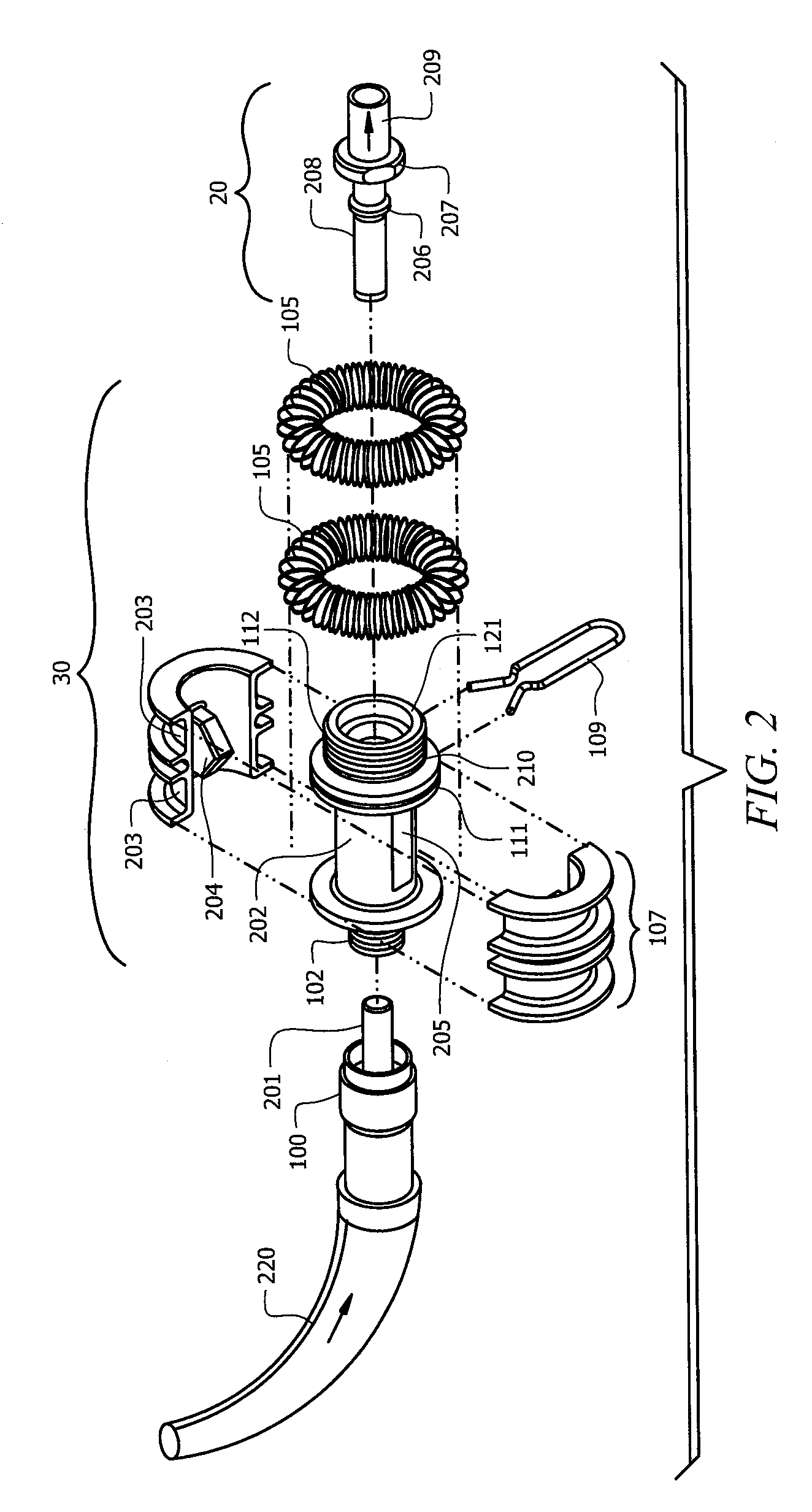
[0008]The present invention is directed to systems and methods that couple together optical devices in a manner that prevents damaging light from escaping the coupling except through the devices. In order to prevent damaging light from coming into contact with the user, the present invention obscures the source optical device by using at least one moveable gate to prevent damaging light from being transmitted outside of the coupling until such time as the target optical device is fully inserted into the coupling, thereby preventing light that could potentially damage a person from escaping the system except through the optical device.
[0009]In order to prevent light from being inappropriately transmitted from the source device, the coupling may utilize any number of embodiments to insure that damaging light is only transmitted beyond the coupling through a proper optical device. Such embodiments incorporate one or more gate shutters that effectively close the light canal of the coupling when the coupling is in its natural condition (i.e., when no optical device is attached to the source optical device. Various embodiments of the invention utilize complimentary redundant components that each act to prevent damaging light from being transmitted outside of the coupling. This redundancy ensures that there is no single point of failure that could result in a complete failure of the coupling.

Problems solved by technology

The use of optical devices in various applications has brought about a need for the capability of coupling optical devices together in situations where the applicable light source from the incoming optical device is already energized, creating a risk that damaging light will endanger those exposed to it.
However, various light sources used in such applications (e.g., light emitting diodes, lasers, etc.) can be harmful to those who may be exposed to the light eminating from the source.
Damaging light can be produced from a variety of sources and can injure a person, such as causing damage to eyesight (e.g., retina, lens).
For example, the coherence and low divergence of laser light means that it can be focused by the eye into an extremely small spot on the retina, quickly (sometimes in less than one second) resulting in localized burning and permanent damage.
Lasers of Class III and above present increasing levels of risk for significant damage of both eyes and skin.
Alternatively, protective gear may be required for any system operator or other person whose eyesight could potentially be exposed to the damaging light.
However, the danger that system operators will not power down the light source when appropriate or fail to use suitable protective gear (or fail to use it properly) in the operation of the system is high.
Also, problems could exist where the coupling between the light source and the target connector fails (sometimes because of a failure to properly interlock the connectors, and sometimes because of mechanical failure).
Such a failure could result in damage to operators and patients.

Method used


Image

  • Optical transmission coupling
  • Optical transmission coupling
  • Optical transmission coupling

Examples


embodiment 700

[0039]FIG. 7 is perspective view of an embodiment 700 of the present invention that utilizes torsion spring gated pins 702-1 and 702-2 that rotate out of the light path to prevent damaging light from being transmitted outside of the coupling body. In one version of this embodiment as seen in FIG. 7A, spring-wound gated pins 701 are inserted into staggered holes through the body of the coupling. The pins are linearly positioned along coupling body 700, and wound with a tension spring (not shown) that acts to allow the rotation of spring-wound pin 701 to a position in which gate tabs 720-1 and 720-2 extend into light canal 730 when the ferrule is not inserted. When the ferrule is inserted into the coupling, the ferrule pushes gate tabs 720-1 and 720-2 outward toward the sides of coupling body 700 causing the spring-wound pins to rotate against force exerted by the torsion springs 703. When the ferrule is removed, the torsion spring forces the pins to return to their natural position i...

embodiment 800

[0040]FIG. 8 shows embodiment 800 of the present invention that utilizes linear springs 802 to rotate gate 805 into light path 806 to prevent damaging light from being transmitted outside of the coupling body when an output optic device is not connected. Gate 805 rotates with pin 804 (which in turn rotates within slots (not shown) in housing 801. Gate 805 is shown in the open position, as though a downstream connector (not shown) were connected to coupling 800. Any configuration of rotation is possible and a plurality of such gates would advantageously be used in a coupling. When an output optic device is inserted into coupling 800, its ferrule pushes against gates 804 to cause the gate to rotate outward toward the sides of coupling body 800 causing the spring-based gates to rotate. When the ferrule is removed, the springs force the gates to return to their resting (closed) positions in which the gates block the light canal of coupling body 800, thereby preventing damaging light fro...

embodiment 90

[0041]FIGS. 9 and 9A show views of an embodiment 90 that utilizes elastomeric housing 901 for supplying the force for controlling the flexing of gates that prevent damaging light from being transmitted outside of the coupling body. Window 902 is used to allow the housing to be molded and to form gates within the housing body for selectively blocking light from being transmitted through the light canal of the coupling at the wrong time.

[0042]FIG. 9A shows light canal 91 having gates 903 positioned therein. Gates 903 are elastomeric and, if desired, can be formed as part of housing 901 as above-discussed. Gates 903 function in the same manner as do the gates in the other embodiments in that when a downstream optical connector is inserted in the distal end of the coupling the ferrule on the inserted optical device pushes open the optic canal by causing the gates to flex outward. Note that the ends of the gates do not necessarily have to touch the sides of the optic canal since the dama...


PUM


Abstract

The present invention is directed to systems and methods that couple together optical devices in a manner that prevents damaging light from escaping the coupling except through the devices. In order to prevent damaging light from coming into contact with the user, the present invention obscures the source optical device by using at least one moveable gate to prevent damaging light from being transmitted outside of the coupling until such time as the target optical device is fully inserted into the coupling, thereby preventing light that could potentially damage a person from escaping the system except through the optical device.

Description

TECHNICAL FIELD[0001]The present invention relates generally to an optical transmission coupling and more particularly to an optical transmission coupling that substantially prevents harmful light from the optical source from prematurely escaping the coupling before the target optical transmission connector is inserted into the coupling.BACKGROUND OF THE INVENTION[0002]The use of optical devices in various applications has brought about a need for the capability of coupling optical devices together in situations where the applicable light source from the incoming optical device is already energized, creating a risk that damaging light will endanger those exposed to it. For example, various systems and devices used for medical purposes incorporate the use of an optical source (for example, a laser) for a variety of applications, including utilizing light to visually determine the location of certain medical devices as they travel through a patient's body. The optical source can be so...

Claims


Application Information

Patent Timeline
IPC IPC(8): G02B6/26
CPCG02B6/3813G02B6/3894G02B6/3849G02B6/3825
Inventor DAVIDSON, DANIELSKIDMORE, JOSEPH E.FINE, RICHARD A.
Owner FUJIFILM SONOSITE
Learn More