
Screen

a technology for screens and screens, applied in the field of screens, can solve the problems of disadvantageous viewing of dim images on the screen, unlikely efficient travel of light, etc., and achieve the effect of reducing the amount of ambient light incident on the screen

Active Publication Date: 2010-04-15
SEIKO EPSON CORP
View PDF1 Cites 9 Cited by
  • Summary
  • Abstract
  • Description
  • Claims
  • Application Information

AI Technical Summary

Benefits of technology

[0006]An advantage of some aspects of the invention is to provide a screen that causes light from a projector to efficiently travel forward with an appropriate angular distribution so that a high-brightness, high-contrast image is provided.

Problems solved by technology

It is therefore a challenge to provide a high-brightness, high-contrast image on a reflective screen even in bright-room environments.
When the amount of light that travels obliquely to the normal to the screen increases, a viewer in front of the screen disadvantageously views a dim image.
As described above, the related art is problematic in that the light unlikely travels in an efficient manner with an appropriate angular distribution in an area in front of the screen.

Method used


Image

  • Screen
  • Screen
  • Screen

Examples


first embodiment

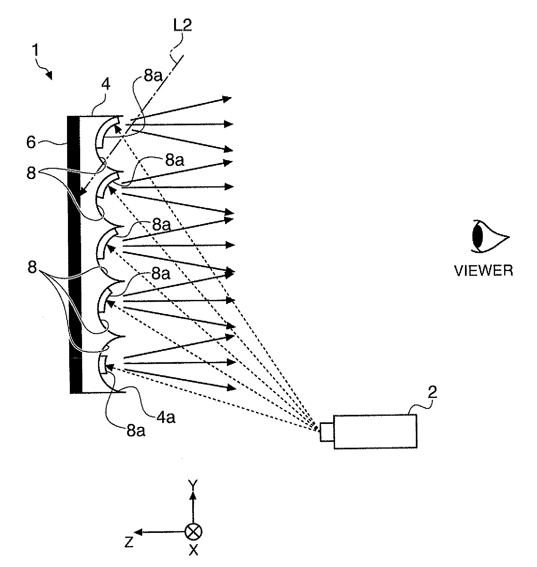
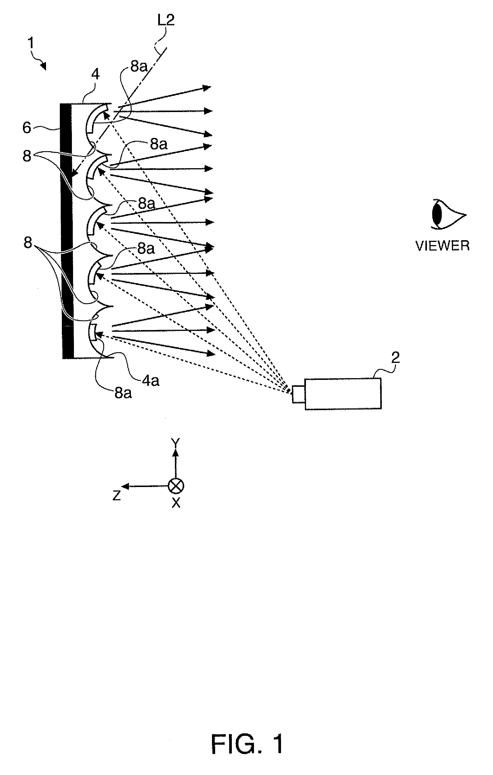
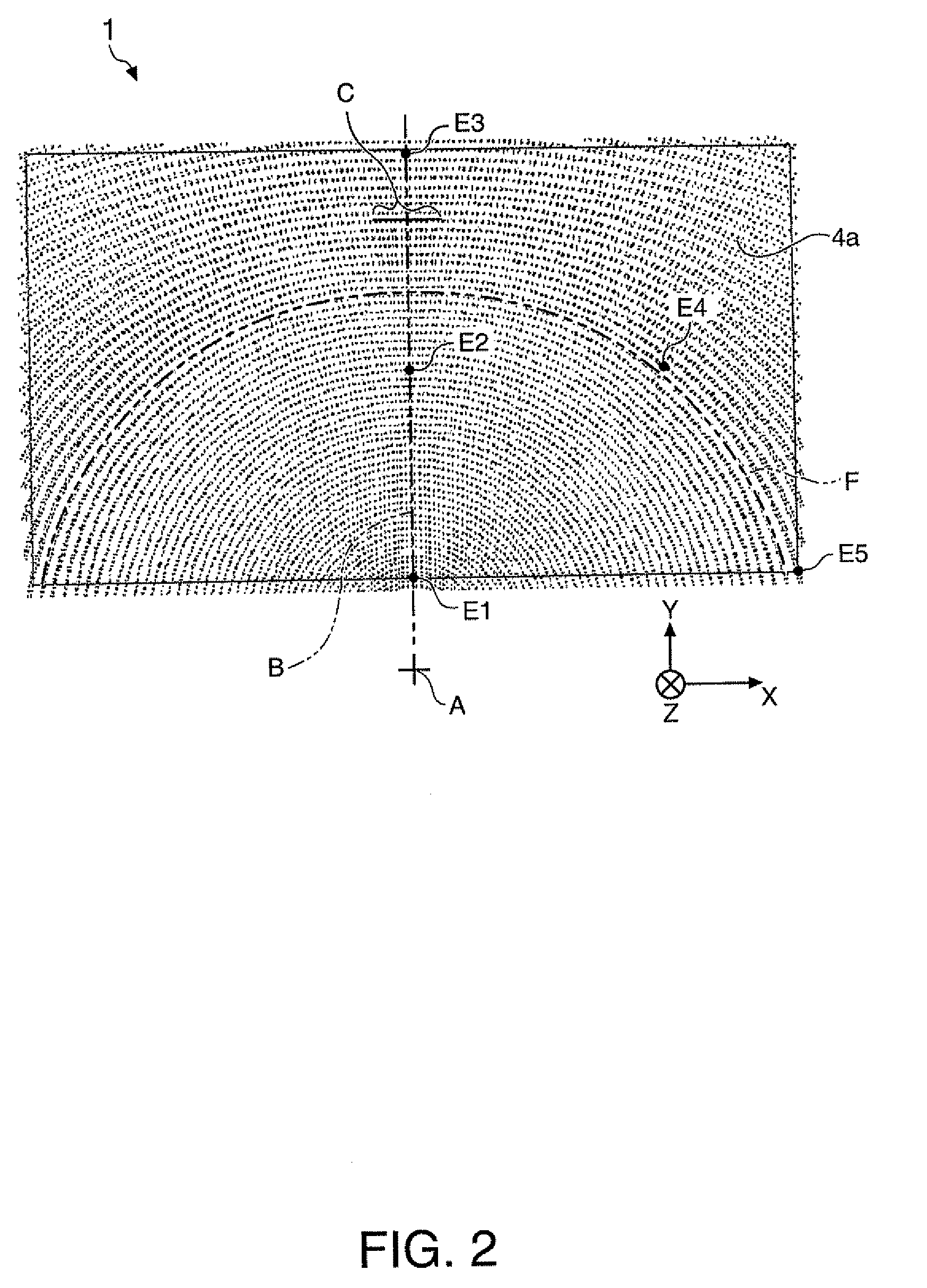
[0038]FIG. 1 diagrammatically shows a cross-sectional configuration of a screen according to a first embodiment of the invention. FIG. 2 diagrammatically shows a plan-view configuration of the screen 1 viewed from a projector 2. The screen 1 is a reflective screen that reflects projection light from the projector 2. The projector 2 is a front-projection projector that projects light according to an image signal. In the description of the embodiment of the present application, it is assumed that a Z axis is an axis along the optical axis of a projection system provided in the projector 2. It is also assumed that an X axis and a Y axis are perpendicular to each other and to the Z axis.

[0039]The screen 1 generally includes a substrate 4 and a light absorbing layer (absorber) 6. The substrate 4 is made of a transparent material that transmits light. A plurality of recesses 8 are densely formed on the surface of the substrate 4 on which the projection light from the projector 2 is incide...


PUM

PropertyMeasurementUnit
angleaaaaaaaaaa
angleaaaaaaaaaa
angleaaaaaaaaaa

Abstract

A screen includes a plurality of concave recesses arranged on a flat surface, wherein the recesses are arranged in such a way that the spacing between adjacent ones of the recesses in the radial direction from a reference point located in the flat surface or a plane extended from the flat surface increase with distance from the reference point.

Description

BACKGROUND[0001]1. Technical Field[0002]The present invention relates to a screen, and particularly to a technology of a screen that reflects light projected from a projector.[0003]2. Related Art[0004]A front-projection projector is used in combination with a reflective screen that projects projection light. A reflective screen can relatively easily provide a high-brightness, high-contrast image in a dark-room environment. On the other hand, in a conference room, a room in a general household, and other bright-room environments, the fact that the screen reflects not only image light but also ambient light causes the portion that should be displayed in black to be whitish black in some cases. This phenomenon is called black floating. It is therefore a challenge to provide a high-brightness, high-contrast image on a reflective screen even in bright-room environments. For example, JP-A-2006-215162 proposes a technology in which convex portions having a unit shape are regularly arranged...

Claims


Application Information

Patent Timeline
Patent Type & Authority Applications(United States)
IPC IPC(8): B32B3/10G02B5/10G03B21/60
CPCB32B3/30Y10T428/24736Y10T428/24661B32B3/085B32B2250/02B32B2307/40B32B2307/406B32B2307/416B32B2551/00
Inventor SHINBO, AKIRAKATSUMA, RYOJI
Owner SEIKO EPSON CORP
Learn More