

Fuel cell and fuel cell fastening device
Patent Information
- Authority / Receiving Office
- US · United States
- Current Assignee / Owner
- TOYOTA JIDOSHA KK
- Publication Date
- 2010-04-15
Smart Images
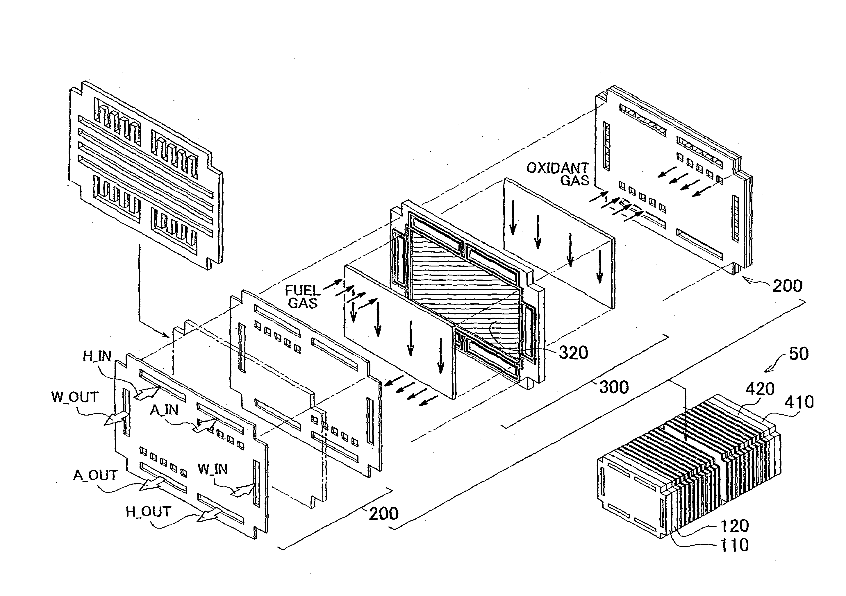
Figure 1 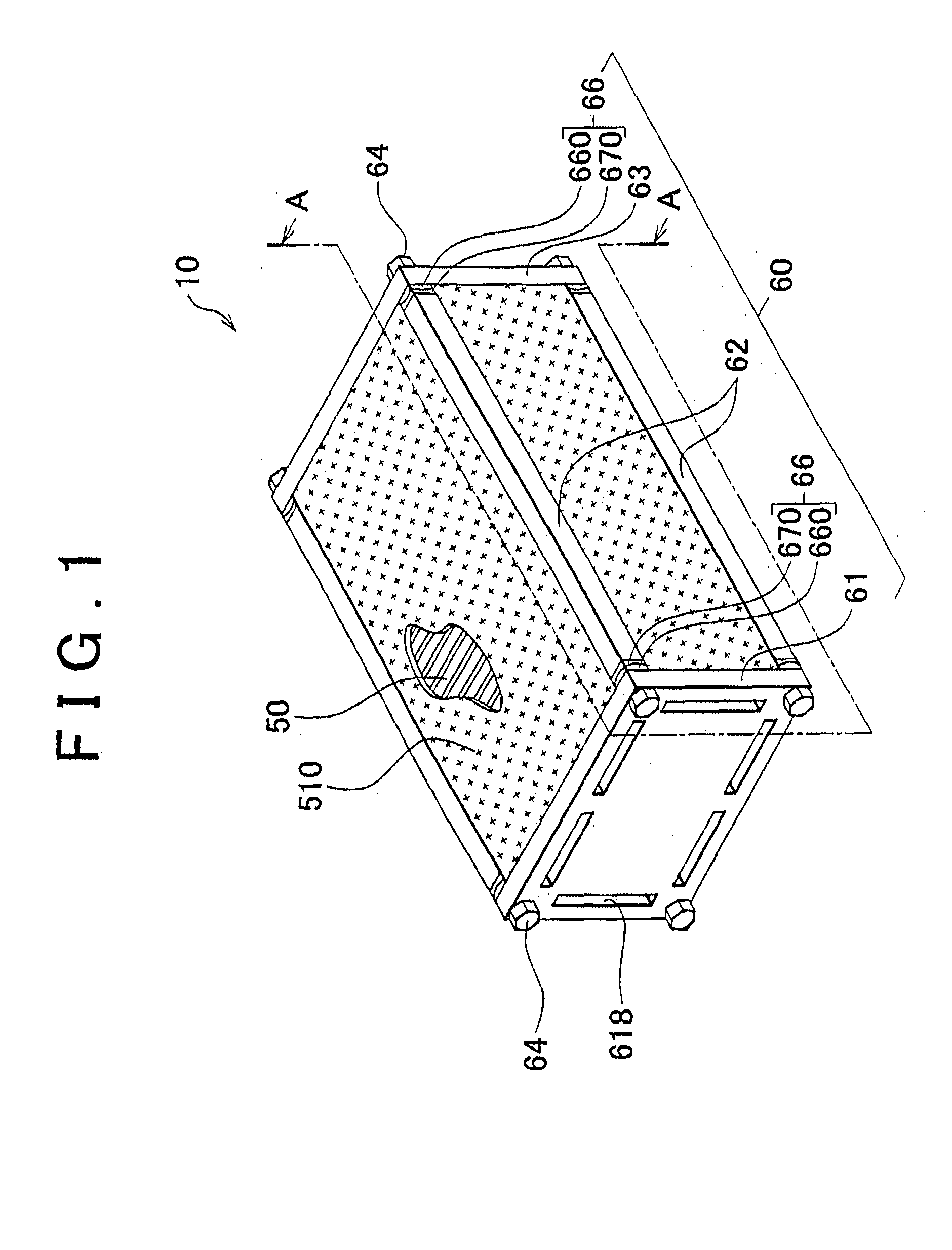
Figure 2 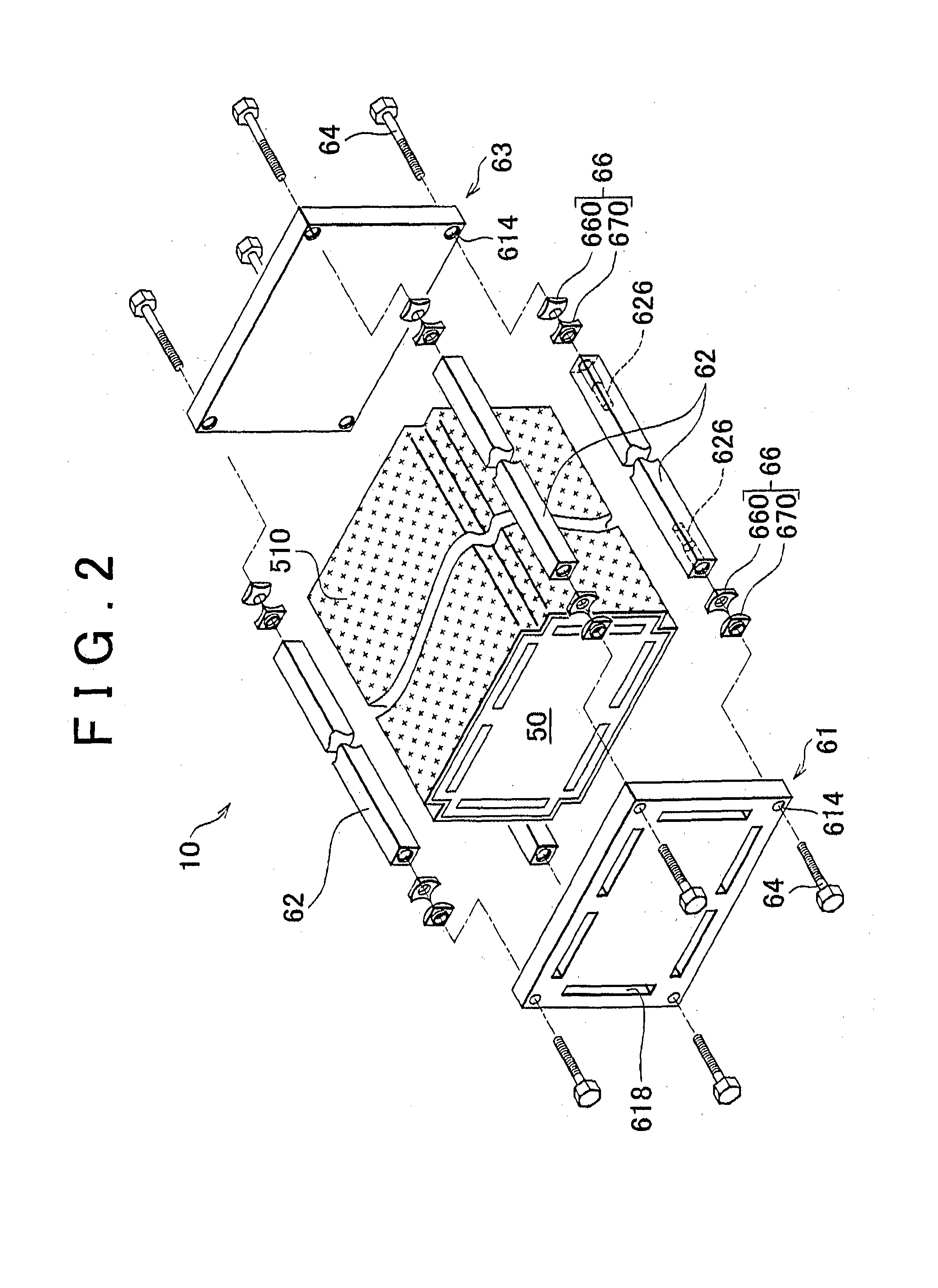
Figure 3
Abstract
Description
BACKGROUND OF THE INVENTION
[0001] 1. Field of the Invention
[0002] The present invention relates to a fuel cell that includes a fuel cell stack in which multiple fuel cell units are stacked on one another and electrochemically generates electricity using reaction gas. In particular, the present invention relates to a structure that fastens the fuel cell stack of the fuel cell.
[0003] 2. Description of the Related Art
[0004] To fasten a fuel cell stack of a fuel cell, the fuel cell sometimes includes a pair of end plates respectively contact both ends of the fuel cell stack in a stacking direction of the fuel cell stack, side plates that extend in the stacking direction and disposed between the pair of end plates, and connecting bolts that connect the end plates and side members. Japanese Patent Application Publication No. 2004-185845 (JP-A-2004-185845) and Japanese Patent Application Publication No, 2006-302900 (JP-A-2006-302900) describe fuel cells in which end plates are connected to sid...