Lancing device

a technology of a lancing device and a cylinder head is applied in the field of lancing devices, which can solve the problems that the lancing device cannot be ejected by an unintended firing, and achieve the effects of reducing vibration during forward movement, preventing rotational components, and reducing pain

Active Publication Date: 2010-04-15
BIONIME
View PDF4 Cites 90 Cited by
  • Summary
  • Abstract
  • Description
  • Claims
  • Application Information

AI Technical Summary

Benefits of technology

[0012]When the safety switch is in the safety position and thus the lancet holder is prevented from being cocked, the lancet cannot be fired from a cocked position with a high speed. By operating the safety switch the user can control the ability of the lancing device of firing the lancet.
[0049]Preferably the inner housing comprises four guide tracks, which guide four corresponding guide ribs in the lancet holder. The guidance if the lancet holder is stabilized in perpendicular lateral directions and the resulting lateral tolerances are much smaller compared with a cylindrical guidance. A rectilinear advancement of the lancet holder reduces the pain during the needle insertion.

Problems solved by technology

Furthermore in a state, where the housing member is open to change the lancet, the lancet cannot be ejected by an unintended firing.

Method used


Image

  • Lancing device
  • Lancing device
  • Lancing device

Examples


embodiment 1

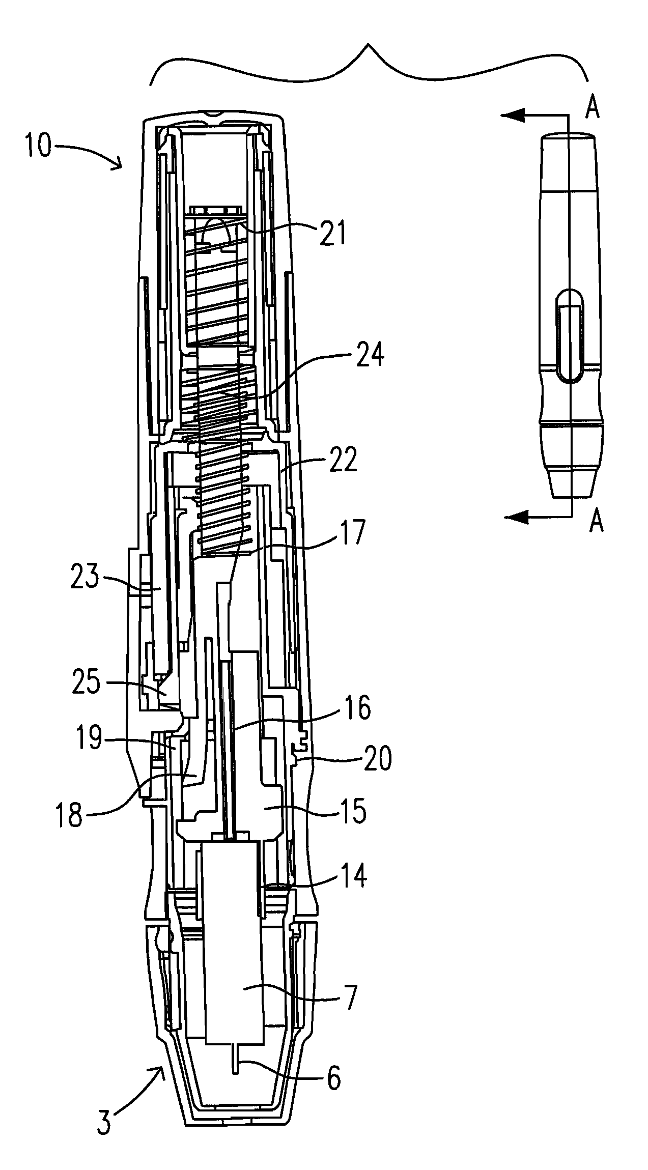
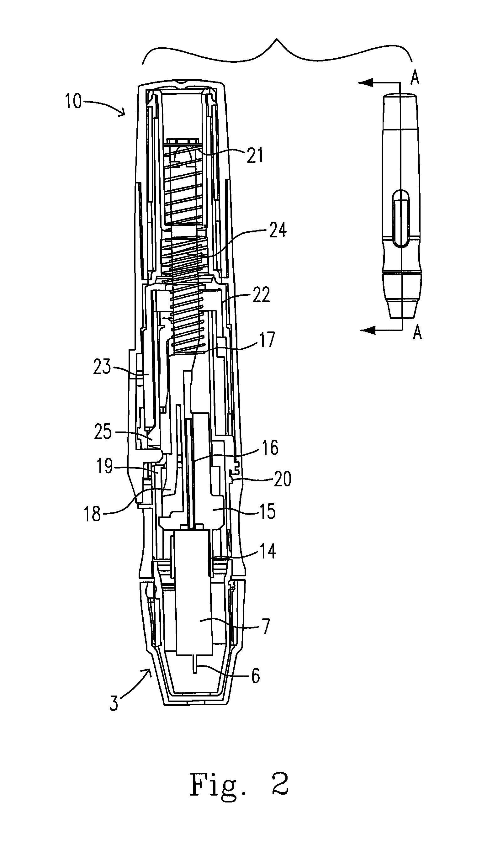
[0100]2. A lancing device further comprising an ejection pin pushing the lancet out of the lancet holder, and an ejection switch moveable between an ejection position and an loading position, wherein the ejection pin is moveable with respect to the lancet holder; the ejection switch allows a relative movement of the ejection pin and the lancet holder for ejecting the lancet when in the ejection position, and the ejection switch does not affect a coupled movement of the ejection pin and the lancet holder when in the loading position.

embodiment 2

[0101]3. A lancing device , wherein the ejection switch in the loading position affords a movement of the ejection pin.

embodiment 3

[0102]4. A lancing device , wherein the ejection pin moves along with a backward movement of the lancet holder.

[0103]5. A lancing device as in Embodiment 2 further comprising a mode switch member, wherein at least one of the safety switch and the ejection switch are mounted on the mode switch member.


PUM


Abstract

A lancing device for ejecting a lancet having a pricking element protruding therefrom along an ejection axis is provided. The lancing device includes a front cap having an opening facing against an object to be pricked, a lancet holder slideable between a cocked position and a pricking position, and a safety switch moveable between a safety position and a passing position, wherein the pricking element extends beyond the opening when the lancet is ejected; the safety switch prevents the lancet holder form being cocked when the safety switch is in the safety position, and the safety switch allows the lancet holder to be cocked and moved when the safety switch is in the passing position.

Description

FIELD OF THE INVENTION[0001]The present invention relates to a lancing device for ejecting a lancet according to the preamble of the independent claims.BACKGROUND OF THE INVENTION[0002]Many medical procedures in use today require a relatively small sample of blood, in the range of 5-50 μl. Normally such a sample is obtained by lancing or piercing the skin at a selected location, such as the finger, to enable the collection of 1 or 2 drops of blood. With the advent of home use tests such as self monitoring of blood glucose, there is a requirement for a simple and safe procedure which can be performed by a person needing to test.[0003]Lancets in conventional use generally have a rigid body and a sterile pricking element, for example a needle, which protrudes from one end. The lancet may be used to pierce the skin, thereby enabling the collection of a blood sample from the opening created. The blood is transferred to a test device or collection device. Blood is most commonly taken from...

Claims


Application Information

Patent Timeline
Patent Type & Authority Applications(United States)
IPC IPC(8): A61B17/32
CPCA61B5/1411A61B5/150022A61B5/150183A61B5/150412A61B5/150503A61B5/15113A61B5/15117A61B5/1513A61B5/1519A61B5/15194
Inventor HUANG, MAO-SUNGHUANG, KUANG-LIMICHEL, THOMASLARSSON, MARITA
Owner BIONIME
Why Eureka
Try Eureka