Vehicle steering apparatus

a steering apparatus and vehicle technology, applied in the direction of underwater vessels, non-deflectable wheel steering, special data processing applications, etc., can solve the problems of reducing the cost of the solution, requiring a large number of wires and a large installation space, and reducing the cost of the unit that includes the brushless motor

Inactive Publication Date: 2010-04-15
JTEKT CORP
View PDF9 Cites 29 Cited by
  • Summary
  • Abstract
  • Description
  • Claims
  • Application Information

AI Technical Summary

Benefits of technology

[0007]It is an object of the invention to provide a vehicle steering apparatus in which a motor is controlled by a new control method that does not require a rotational angle sensor.
[0008]An aspect of the invention relates to a vehicle steering apparatus in which a driving force is supplied to a steering mechanism for a vehicle from a motor that includes a rotor and a stator that faces the rotor. A current drive unit drives the motor based on an axis current value in a rotating coordinate system that rotates in accordance with a control angle that is a rotational angle used in a control. A control angle calculation unit obtains a current value of the control angle by adding an addition angle to an immediately preceding value of the control angle in each predetermined calculation cycle. A steering angle detection unit detects a steering angle of the steering mechanism. A torque detection unit detects a steering torque applied to an operation member that is operated to steer the vehicle. A command steering torque setting unit sets a command steering torque that corresponds to the steering angle detected by the steering angle detection unit based on a predetermined steering angle-torque characteristic. An addition angle calculation unit calculates the addition angle based on the deviation of the detected steering torque detected by the torque detection unit from the command steering torque set by the command steering torque setting unit. The addition angle based on the deviation is changed when a predetermined condition is satisfied.

Problems solved by technology

However, a resolver is expensive, and needs a large number of wires and a large installation space.
Therefore, using a resolver as a rotational angle sensor hinders reduction in cost and size of a unit that includes a brushless motor.
When the rotor is at a standstill or rotating at a considerably low speed, it is not possible to estimate the induced voltage.

Method used


Image

  • Vehicle steering apparatus
  • Vehicle steering apparatus
  • Vehicle steering apparatus

Examples


first embodiment

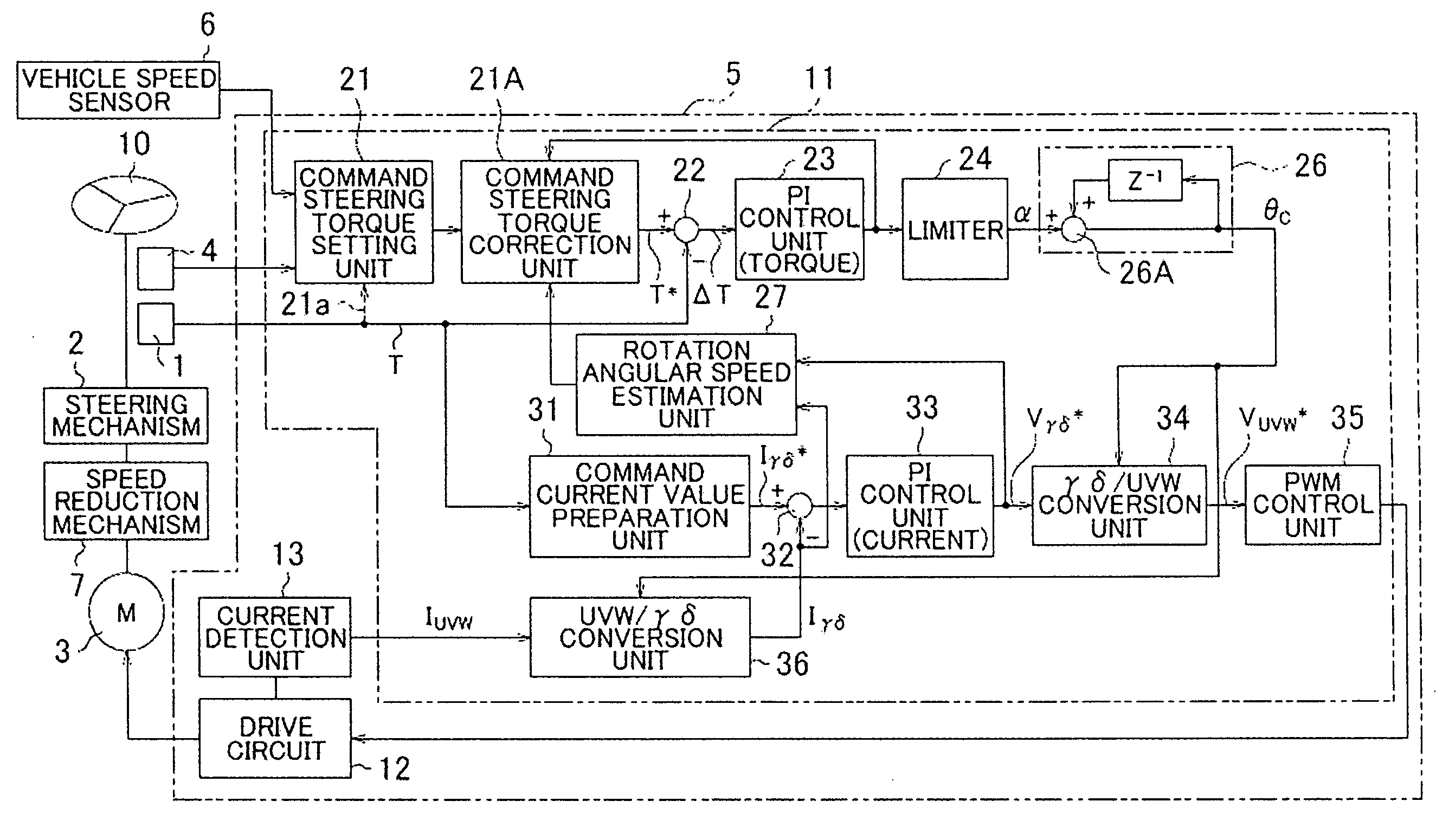
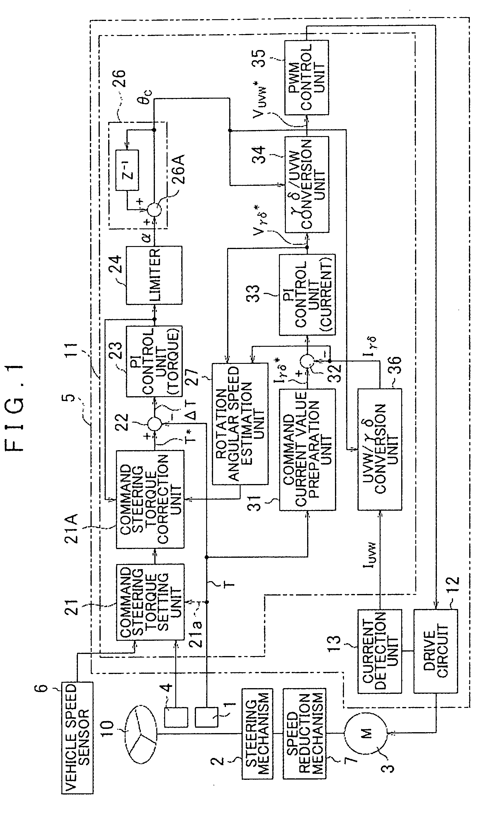
[0023]Hereafter, example embodiments of the invention will be described with reference to the accompanying drawings. FIG. 1 is a block diagram illustrating the electrical configuration of an electric power steering apparatus used as a vehicle steering apparatus according to the invention. The electric power steering apparatus includes a torque sensor 1 that detects the steering torque T that is applied to a steering wheel 10 that serves as an operation member used to steer a vehicle, a motor 3 (brushless motor) that applies a steering assist force to a steering mechanism 2 of the vehicle via a speed reduction mechanism 7, a steering angle sensor 4 that detects the steering angle that is the rotational angle of the steering wheel 10 (corresponding the steering angle of the steering mechanism 2), a motor control unit 5 that controls driving of the motor 3, and a vehicle speed sensor 6 that detects the speed of the vehicle in which the electric power steering apparatus is mounted.

[0024...

second embodiment

[0065]FIG. 8 is a flowchart illustrating the routine of an electric power steering apparatus (vehicle steering apparatus) according to the invention. FIGS. 1 to 6 are used again in the description of the second embodiment. FIG. 8 shows the routine executed by the command steering torque setting unit 21 to set the command steering torque T*.

[0066]In the second embodiment, the damping characteristic shown in FIG. 4B is not used, and only the normal characteristic shown in 4A is used. The command steering torque setting unit 21 sets the command steering torque T* that corresponds to the steering angle based on the normal characteristic shown in FIG. 4A. As indicated by a dashed-two dotted line 21a in FIG. 1, the steering torque detected by the torque sensor 1 is provided to the command steering torque setting unit 21. The command steering torque setting unit 21 determines whether the driver takes hands off the steering wheel 10 based on the detected steering torque T. If it is determin...

third embodiment

[0072]FIG. 9 is a block diagram illustrating the configuration of an electric power steering apparatus (vehicle steering apparatus) according to the invention. In FIG. 9, the same reference numerals are assigned to the same portions as those in FIG. 1.

[0073]In the third embodiment, a damping control unit 60 that prepares the detected torque correction value Tr for the detected steering torque T, and the command current correction value Ir for the γ-axis command current value Iγ* is provided to realize the damping control. The detected torque correction value Tr is subtracted from the detected steering torque T by a detected torque correction unit 61. The detected steering torque T after correction is provided to the torque deviation calculation unit 22. The command current correction value Ir is subtracted from the γ-axis command current value Iγ* by the γ-axis command current correction unit 62. The γ-axis command current value Iγ* after correction is provided to the current deviat...


PUM


Abstract

A motor is driven based on an axis current value in a rotating coordinate system that rotates in accordance with a control angle that is a rotational angle used in a control. The control angle is calculated by adding an addition angle to an immediately preceding value of the control angle in each predetermined calculation cycle. A command steering torque is set based on a predetermined steering angle-torque characteristic. The addition angle is calculated based on the deviation of a detected steering torque from a command steering torque. The addition angle based on the deviation is changed when a predetermined condition is satisfied.

Description

INCORPORATION BY REFERENCE[0001]The disclosure of Japanese Patent Application No. 2008-266344 filed on Oct. 15, 2008 including the specification, drawings and abstract is incorporated herein by reference in its entirety.BACKGROUND OF THE INVENTION[0002]1. Field of the Invention[0003]The invention relates to a vehicle steering apparatus that includes a motor control unit used to drive a brushless motor.[0004]2. Description of the Related Art[0005]An example of a vehicle steering apparatus is an electric power steering apparatus. A brushless motor is used as a drive source that supplies a driving force to a steering mechanism of a vehicle. A motor control unit that controls driving of a brushless motor is usually configured to control the electric current that is supplied to a motor based on the output from a rotational angle sensor that detects the rotational angle of a rotor. As a rotational angle sensor, a resolver that outputs a sine-wave signal and a cosine-wave signal that corre...

Claims


Application Information

Patent Timeline
Patent Type & Authority Applications(United States)
IPC IPC(8): G06F19/00B62D6/00B62D101/00B62D113/00B62D117/00B62D119/00H02P6/06H02P6/08H02P6/18H02P6/182H02P6/28
CPCB62D5/0472B62D5/046
Inventor KARIATSUMARI, YUJISHIMIZU, YOSHINOBUKOMATSU, HAYATO
Owner JTEKT CORP
Why Eureka
Try Eureka