Supercharge Your Innovation With Domain-Expert AI Agents!

Instant reading oil dipstick

a technology of oil dipsticks and dipsticks, which is applied in the direction of liquid/fluent solid measurement, instruments, machines/engines, etc., can solve the problems of dripping oil and confused reading of conventional metal strip dipsticks, and achieve the effect of easy reading

Inactive Publication Date: 2010-04-22
ARMISTEAD JOHN ANDERSON
View PDF13 Cites 8 Cited by
  • Summary
  • Abstract
  • Description
  • Claims
  • Application Information

AI Technical Summary

Benefits of technology

[0007]To allow the oil to flow into the plastic tube, the vent hole must be open the entire time that the dipstick is inserted. But by placing a small brass slide valve just above the vent hole, such slide valve can be made to close over the vent hole, almost instantly, when the dipstick is removed. With the vent hole thus closed, the representative depth of the oil inside the plastic tube is prevented from draining back out of the open end of the tube at its bottom. Such is because a vacuum is created in the upper tube which is sufficiently strong to counter the weight of the oil that is now trapped in the plastic tube.
[0008]When the instant reading oil dipstick is withdrawn from the metal dipstick tube, the oil level can be determined whether or not there is a rag or tissue available for wiping off the dipstick. Because the plastic is translucent, the color of the oil in the tube is immediately discernable. If the oil being used happens to be water clear, the level can be determined by looking for the darker looking curved top of the oil surface. That surface refracts the light so that the top is visible as a darker area. Additionally, because the oil also coats the outside of the dipstick, even if no wiping has been done, the level of the oil around the plastic tube is more easily read than on a flat metal strip that must be tilted in the light to see the shine of the oil.

Problems solved by technology

Spattered or dripped oil can confuse the reading of conventional metal strip type dipsticks.

Method used


Image

  • Instant reading oil dipstick
  • Instant reading oil dipstick

Examples


Embodiment Construction

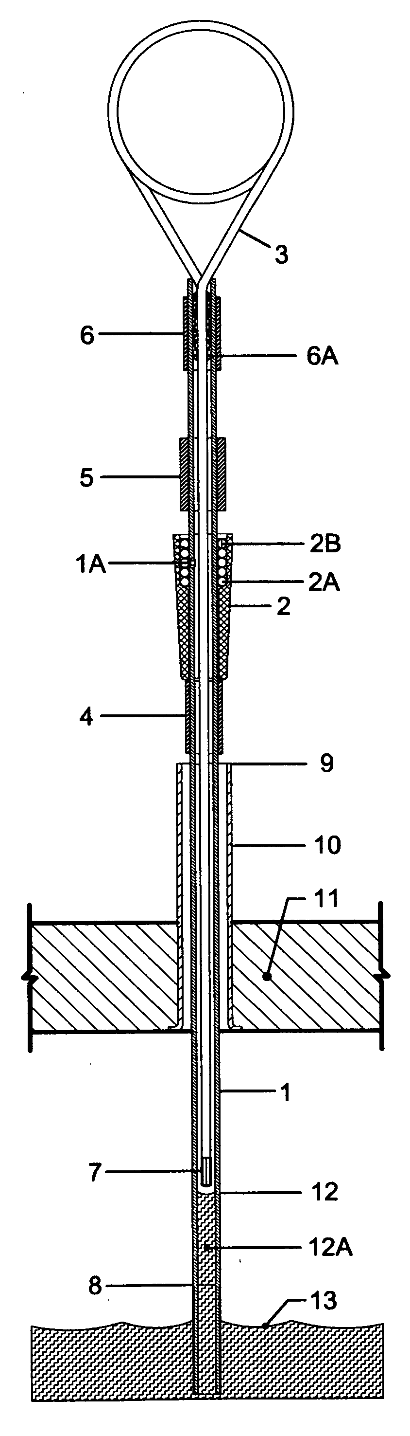
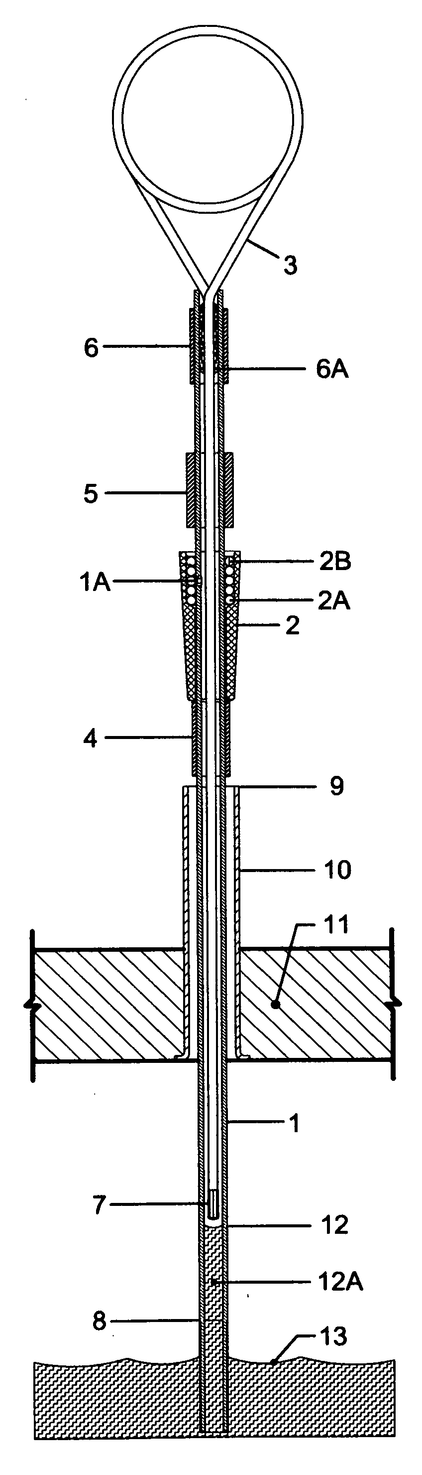
[0011]The present invention measures the level of oil, 13, inside of a vehicle's crankcase, 11, by inserting a small, translucent, high-temperature-resistant, fluoroplastic tubing, 1, through the engine's metal dipstick tubing, 10, and physically extracting a column of oil, 12A, which corresponds to the depth of oil in the reservoir of the crankcase, 13. Such is made possible by the fact that the tubing, 1, is sealed air-tight by thermal resistant cyanoacrylate gel glue, 6A. And a single small vent hole, 1A, will allow the oil in the reservoir below surface, 13, to come to a corresponding level, 12, inside of the dipstick tubing, 1.

[0012]The drawing shows vent hole, 1A, covered over by a machined brass slide valve, 2. Such slide valve, 2, has internal O-rings, 2A, below, and 2B, above, which are compressed against both the O. D. of tubing, 1, and the I. D. of slide valve, 2. The spacing of such O-rings, 2A and 2B, is maintained via three identical O-rings which will provide addition...


PUM


Abstract

The present instant reading oil dipstick automatically extracts a representative column of oil from the crankcase oil reservoir. Such is done inside of a translucent fluoroplastic tube. A machined brass slide valve, with sealing O-rings, fits inside of the metal dipstick tubing leading into the engine crankcase. When the dipstick is withdrawn for checking oil level, the slide valve automatically closes over an air vent in the plastic tubing, thus preventing the oil that is inside the bottom of the tubing from running out. The oil level can be ascertained, easily—even in low light levels—without having to wipe off the oil from the outside of the dipstick, and without having to reinsert the dipstick one or more times.

Description

BACKGROUND OF THE INVENTION[0001]The most commonly used conventional oil dipsticks are thin metal strips that extend into the oil of a vehicle's crankcase. During the running of the engine, oil is sprayed, or gets splattered, on the metal strip, above the oil level that is in the crankcase oil reservoir. To accurately read the level of the oil using conventional metal dipsticks, the checker must remove the dipstick from the metal dipstick tube, wipe it off with a rag or tissue, then, fully reinsert the dipstick. That conventional dipstick must then be withdrawn a second time, while the checker looks for a film of oil that corresponds to the level of oil that has settled into the oil reservoir.[0002]Fresh oil—and especially synthetic oils—are nearly clear in color. With those oils the only way to determine the level is to tilt the dipstick back and forth in the light to look for shine differences between the metal that's coated in oil, and the remaining metal portion that the checker...

Claims


Application Information

Patent Timeline
Patent Type & Authority Applications(United States)
IPC IPC(8): G01F23/04
CPCG01F23/045G01F23/04
Inventor ARMISTEAD, JOHN ANDERSON
Owner ARMISTEAD JOHN ANDERSON
Features
  • R&D
  • Intellectual Property
  • Life Sciences
  • Materials
  • Tech Scout
  • Unparalleled Data Quality
  • Higher Quality Content
  • 60% Fewer Hallucinations
Learn More