End effector for mobile remotely controlled robot

a remote control robot and end effector technology, applied in the direction of mechanical control devices, process and machine control, instruments, etc., can solve the problems of large gears, premature failure, and significant increase in weight, so as to reduce the extent (axial length) of the end effector unit, facilitate co-axial alignment, and reduce the sag and twisting of the gripper fingers.

Active Publication Date: 2010-04-22
FOSTER-MILLER
View PDF41 Cites 46 Cited by
  • Summary
  • Abstract
  • Description
  • Claims
  • Application Information

AI Technical Summary

Benefits of technology

[0007]It is a further object of this invention to provide such an improved end effector gripper for a mobile, remotely controlled robot which reduces sag and twisting of the gripper fingers relative to their pivot axis.
[0008]It is a further object of this invention to provide such an improved end effector gripper for a mobile, remotely controlled robot which reduces the extent (axial length) of the end effector unit to facilitate co-axial alignment with robot wrist axis.
[0009]It is a further object of this invention to provide such an improved end effector gripper for a mobile, remotely controlled robot having a folded construction which allows the end effector to be mounted co-axially with the robot arm and wrist for enabling in-line wrist rotation with axial compactness.
[0010]The invention results from the realization that a strong yet compact end effector for a mobile, remotely controlled robot can be achieved with a drive subsystem that drives gear segments fixed to respective fingers for increasing the torque applied through the fingers without the normally associated increase in size; and further that a bilateral pivot pin can improve consistency and rigidity of finger operation; and that the end effector compactness can be further improved using a folded motor gear reducer drive (package).

Problems solved by technology

One problem with large, strong grippers is that larger gears are needed to drive the gripper fingers with sufficient torque to realize a strong grip force.
But larger gears translate to larger end effector units and significant increase in their weight.
Another issue with present grippers is that the gripper fingers can sag or twist on their pivot axis causing premature failure and less than optimum gripping function.
Yet another issue with end effector grippers is the need to keep the motor / reduction gear package small and compact to keep down the size of the end effector unit, while still providing a strong grip force and rapid gripper closing / opening.

Method used


Image

  • End effector for mobile remotely controlled robot
  • End effector for mobile remotely controlled robot
  • End effector for mobile remotely controlled robot

Examples


Embodiment Construction

[0025]Aside from the preferred embodiment or embodiments disclosed below, this invention is capable of other embodiments and of being practiced or being carried out in various ways. Thus, it is to be understood that the invention is not limited in its application to the details of construction and the arrangements of components set forth in the following description or illustrated in the drawings. If only one embodiment is described herein, the claims hereof are not to be limited to that embodiment. Moreover, the claims hereof are not to be read restrictively unless there is clear and convincing evidence manifesting a certain exclusion, restriction, or disclaimer.

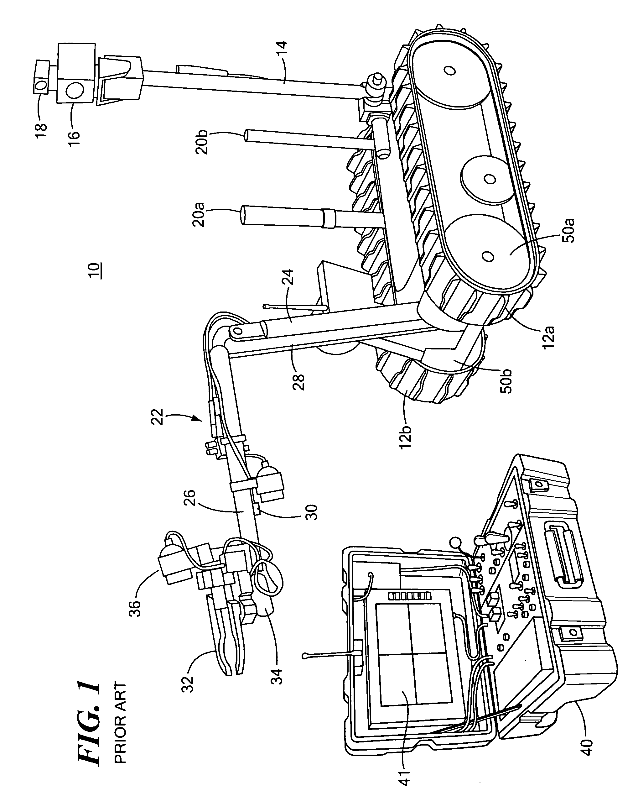
[0026]FIG. 1 shows a mobile, remotely controlled robot 10 driven by tracks 12a and 12b in accordance with one particular example of a robot in accordance with the subject invention. Robot 10 includes deployable mast 14, camera 16, light 18, antennas 20a and 20b, and arm assembly 22. Arm assembly 22 includes lower arm 24 and...


PUM


Abstract

An end effector for a mobile, remotely controlled robot includes first and second fingers; each finger fixed to a gear segment for rotation therewith; and a drive subsystem driving the gear segments and the associated fingers between open and closed positions.

Description

FIELD OF THE INVENTION[0001]This invention relates to a mobile, remotely controlled robot, and more particularly to such a mobile, remotely controlled robot with an improved end effector gripper.BACKGROUND OF THE INVENTION[0002]Mobile, remotely controlled robots are becoming increasingly popular for use by the military, SWAT units, and police and fire departments. The applicants'0 TALON® robot, for example, includes an arm with an end effecter, several cameras, several antennas, and a deployable mast. Frequently the end effector is a gripper, e.g. a pair of jaws that can be opened and closed on command to grasp objects such as debris, hazardous material, unexploded ordinance and the like. The larger robots even have the capability to grip an injured, downed, person by some personal paraphernalia such as a shirt collar and drag them out of harm's way to safety. One problem with large, strong grippers is that larger gears are needed to drive the gripper fingers with sufficient torque ...

Claims


Application Information

Patent Timeline
Patent Type & Authority Applications(United States)
IPC IPC(8): B25J18/00
CPCY10T74/20305B25J15/0213
Inventor ALBIN, SCOTT R.FISK, ALLAN T.
Owner FOSTER-MILLER
Why Eureka
Try Eureka