Slip Seal Diaphragm For Spring Brake Actuator

a technology of spring brake actuator and diaphragm, which is applied in the direction of brake cylinder, braking system, machine/engine, etc., can solve the problems of increasing unable to reach the maximum for the operation of the brake, and the increase in the air pressure in the spring chamber is highly undesirable, so as to reduce the stress on the diaphragm, prevent distortion, and ensure the effect of brake system longevity

Active Publication Date: 2010-04-22
HALDEX BRAKE
View PDF13 Cites 17 Cited by
  • Summary
  • Abstract
  • Description
  • Claims
  • Application Information

AI Technical Summary

Benefits of technology

The patent describes a brake system design that allows for the attachment of a pushrod to a spring piston or a separate fixed plate, eliminating the need for a fixed joint to permanently attach the diaphragm to the pushrod. This design also includes a diaphragm with a compressive seal element and a pressure activated lip seal element that can slide along the center pushrod. The system uses air pressure to engage the lip seal element and compress the parking spring, releasing the parking or emergency brakes and allowing the vehicle to move. The technical effects of this design include improved durability and longevity of the brake system and simplified assembly process.

Problems solved by technology

The technical problem addressed in this patent text is the need to reduce stress on the diaphragm in air brake systems for heavy-duty vehicles, while also eliminating the need for a center rod return spring. This is achieved by developing a system that reduces stress at the diaphragm interface and provides longevity to the brake system.

Method used


Image

  • Slip Seal Diaphragm For Spring Brake Actuator
  • Slip Seal Diaphragm For Spring Brake Actuator
  • Slip Seal Diaphragm For Spring Brake Actuator

Examples


Embodiment Construction

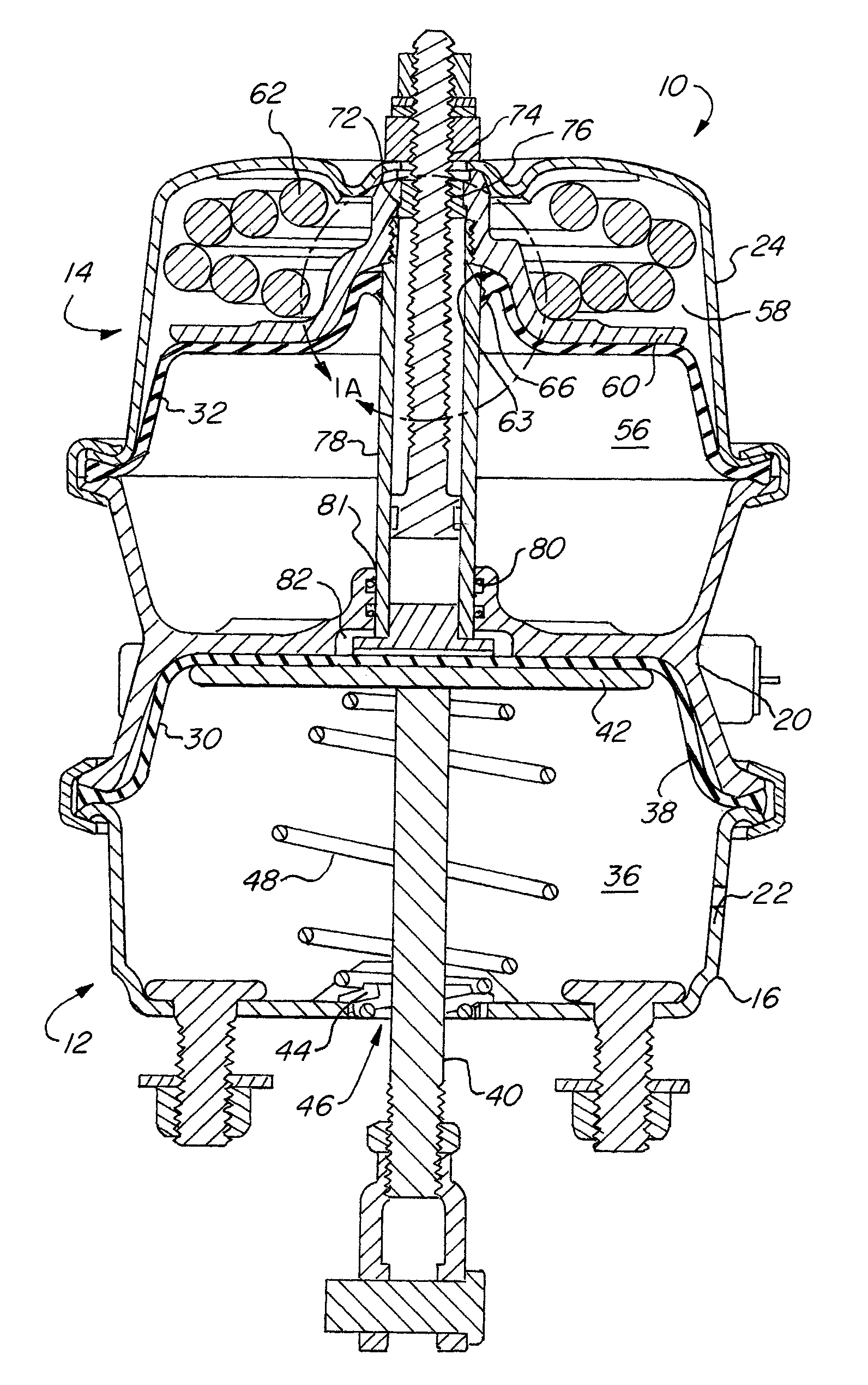
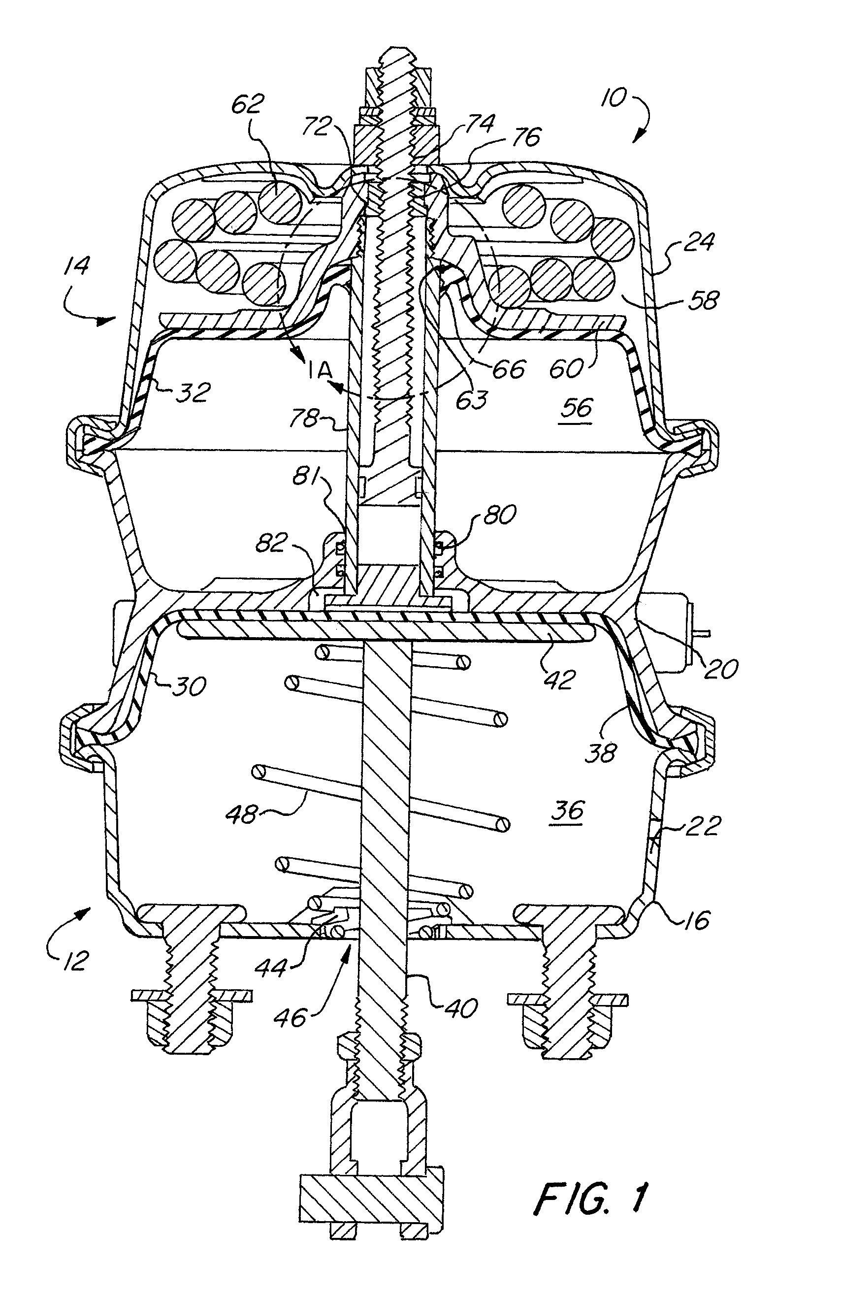
[0024]FIG. 1 illustrates a tandem-type air-operated brake actuator 10 comprising a service brake section 12 in combination with a spring brake section 14. The service brake section 12 applies and releases the service or operating brakes of a vehicle. The spring brake section 14 is used to apply the emergency or parking brakes of the vehicle.

[0025]Both the service brake section 12 and the spring brake section 14 comprise a pressure chamber 38 and 56, which are formed by an adapter housing 20 to which are coupled a stud housing 22 and a spring housing 24, respectively. The adapter housing 20 defines a common dividing wall separating the service brake pressure chamber 38, from the spring brake pressure chamber 56 while forming a portion of each.

[0026]Movable members, which in this embodiment include elastomeric diaphragms 30, 32, span the interior of the service and spring pressure chamber 38 and 56, respectively, by having a peripheral edge of the diaphragm compressibly retained betwe...


PUM


Abstract

A brake actuator system of a vehicle comprising a diaphragm design with a hole and sealing element in the center. The design allows for the sealing element to seal and slide on the outer diameter of the center pushrod for the exposed length. This eliminates the need for a fixed joint to permanently attach the diaphragm to the center pushrod, and allows for the pushrod to be attached to the spring piston or a separate fixed plate and reduces stress of the diaphragm at its interface.

Description


Claims


Application Information

Patent Timeline
Owner HALDEX BRAKE
Why Eureka
Try Eureka