Safety dispensing system for hazardous substances

a technology of safe dispensing system and hazardous substances, applied in the direction of packaging, packaging foodstuffs, packaged goods, etc., can solve the problems of contaminated filters being dangerous to handle, exposure to handling medical technicians or other affected persons, and not enough fluids being transferred from vials, etc., to reduce the likelihood of inadvertent release

Inactive Publication Date: 2011-08-16
INFUSIVE TECH LLC
View PDF391 Cites 62 Cited by
  • Summary
  • Abstract
  • Description
  • Claims
  • Application Information

AI Technical Summary

Benefits of technology

[0040]As part of the valve assembly, a cannula subassembly with a make-before-break seal connection that provides seal contact before cannula piercing of a vial membrane which provides access via the cannula to medicine within the vial. To further reduce likelihood of substance exposure external to the vial and valve assembly, a filter may be affixed to the cannula, similar to the filter of the ChemoBloc® Vial Venting System, distributed by Kendall.LTP, of Tyco / Healthcare. As a practical matter, nearly all liquid transfer through the valve assembly may be accomplished by drawing liquid (applying pressures which are generally less than ambient air pressure) from one site to another through the valve as a considered preferred alternative to using positive pressure therefore. In all cases, any positive pressure resident in the valve assembly and attached parts is not greater than pressure required to displace a stem and associated plunger of a syringe which is in communication with the source of the resident pressure.
[0044]At the location of ultimate use, the protective cap may be removed and the associated pre-flush tube connected to a dispensing site. Note, that the integrity of the liquid flush interface is preserved by the cap and occluding crimp. Note also, that flush resident in the pre-flush tube is dispensed first, then the medicine is dispensed and, finally, flush from the proximal chamber of the multi-chamber syringe is dispensed. So performed, the finally dispensed flush acts to irrigate and so cleanse the connection where the pre-flush tube is connected to the dispensing site, thereby providing a site “rinsed and cleansed” of hazardous liquid for less dangerous handling.
[0057]Accordingly, it is a primary object to provide an apparatus which can be used to transfer hazardous liquid from a vial to a site of use without exposing contents of the vial exteriorly.
[0061]It is an important object to provide a hermetically sealed hazardous material transfer system wherethough fluids are transferred at pressures less than surrounding ambient pressure to reduce likelihood of inadvertent release of hazardous to the ambient environment.

Problems solved by technology

For many medicines, it is not enough that fluids be transferred from a vial to a syringe aseptically.
There are classes of medical fluids which are so caustic and hazardous that any exposure to a handling medical technician or other affected person could have serious negative consequences.
As well, trapped aerosols in filters make so contaminated filters dangerous to handle.
However, further analysis of methods associated with Andréasson makes apparent that even an unprotected connecting element, such as a luer fitting associated with a delivery syringe provides potential for a considerable hazard.

Method used


Image

  • Safety dispensing system for hazardous substances
  • Safety dispensing system for hazardous substances
  • Safety dispensing system for hazardous substances

Examples


Embodiment Construction

[0087]In this description, when the term proximal is used relative to a part or the segment of a device, it is a part which is in closer proximity to a user of the device. The term distal refers to a part or segment generally away from the user. Reference is now made to the embodiments illustrated in FIGS. 1-23 wherein like numerals are used to designate like parts throughout.

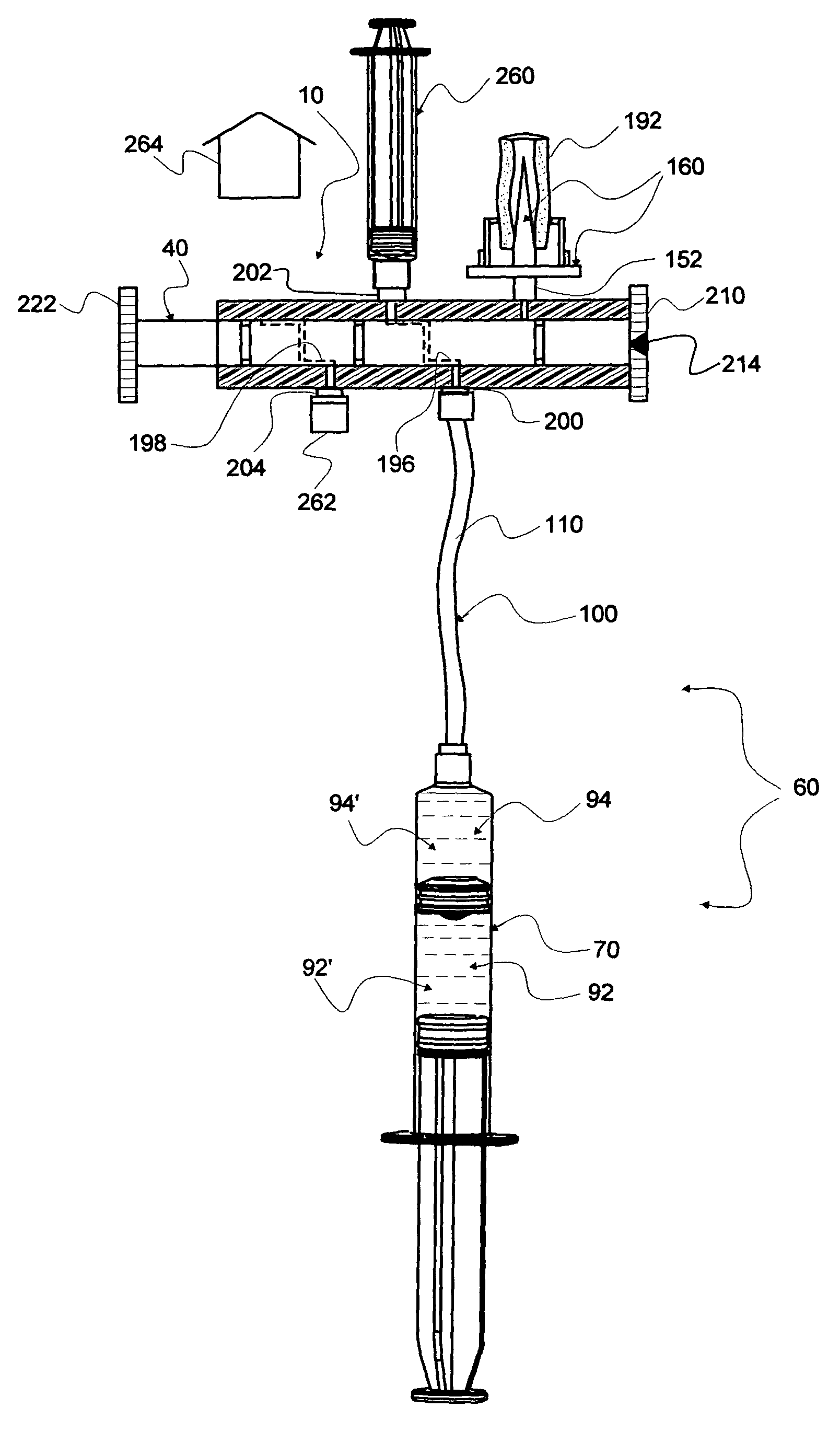
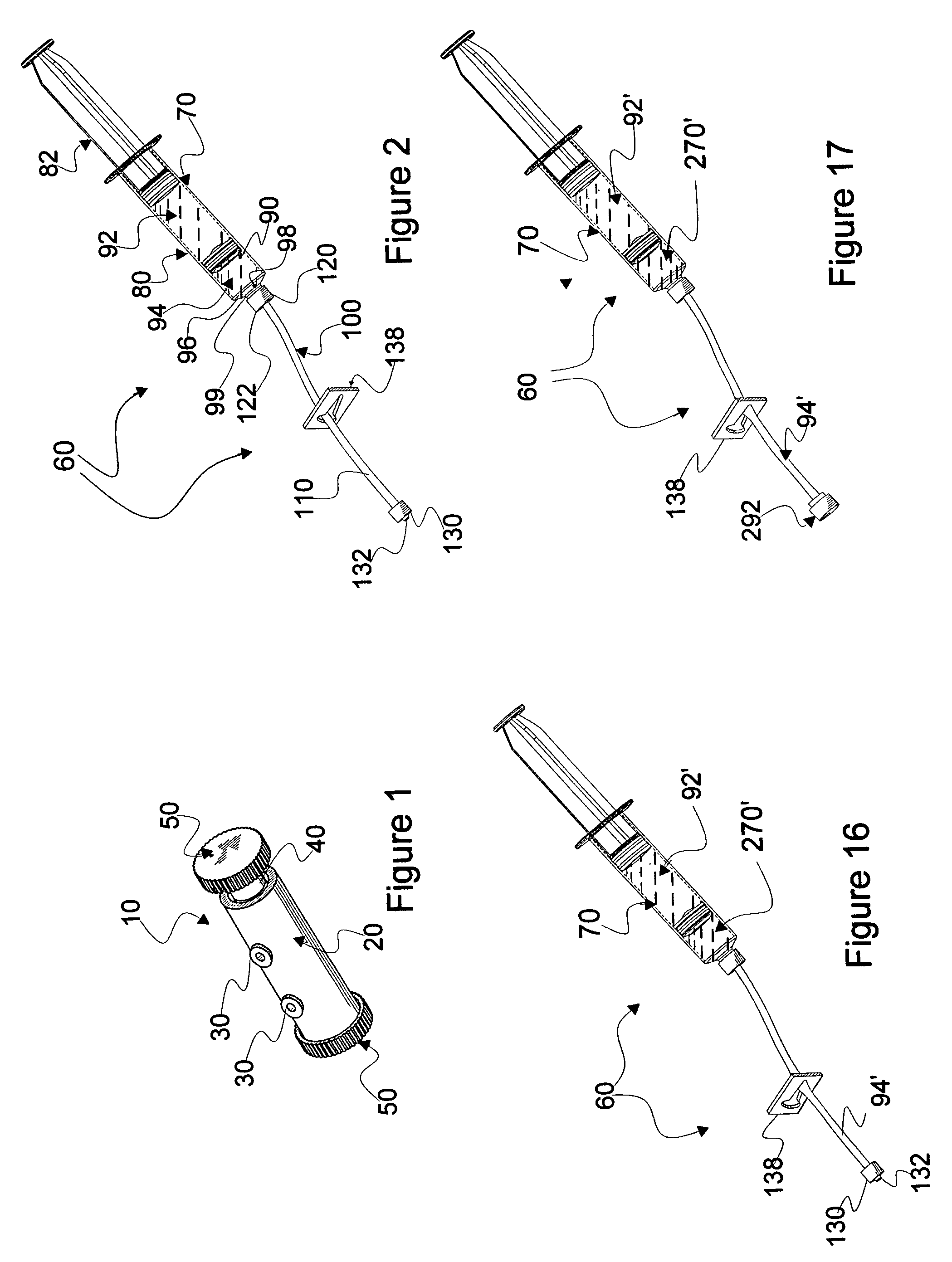
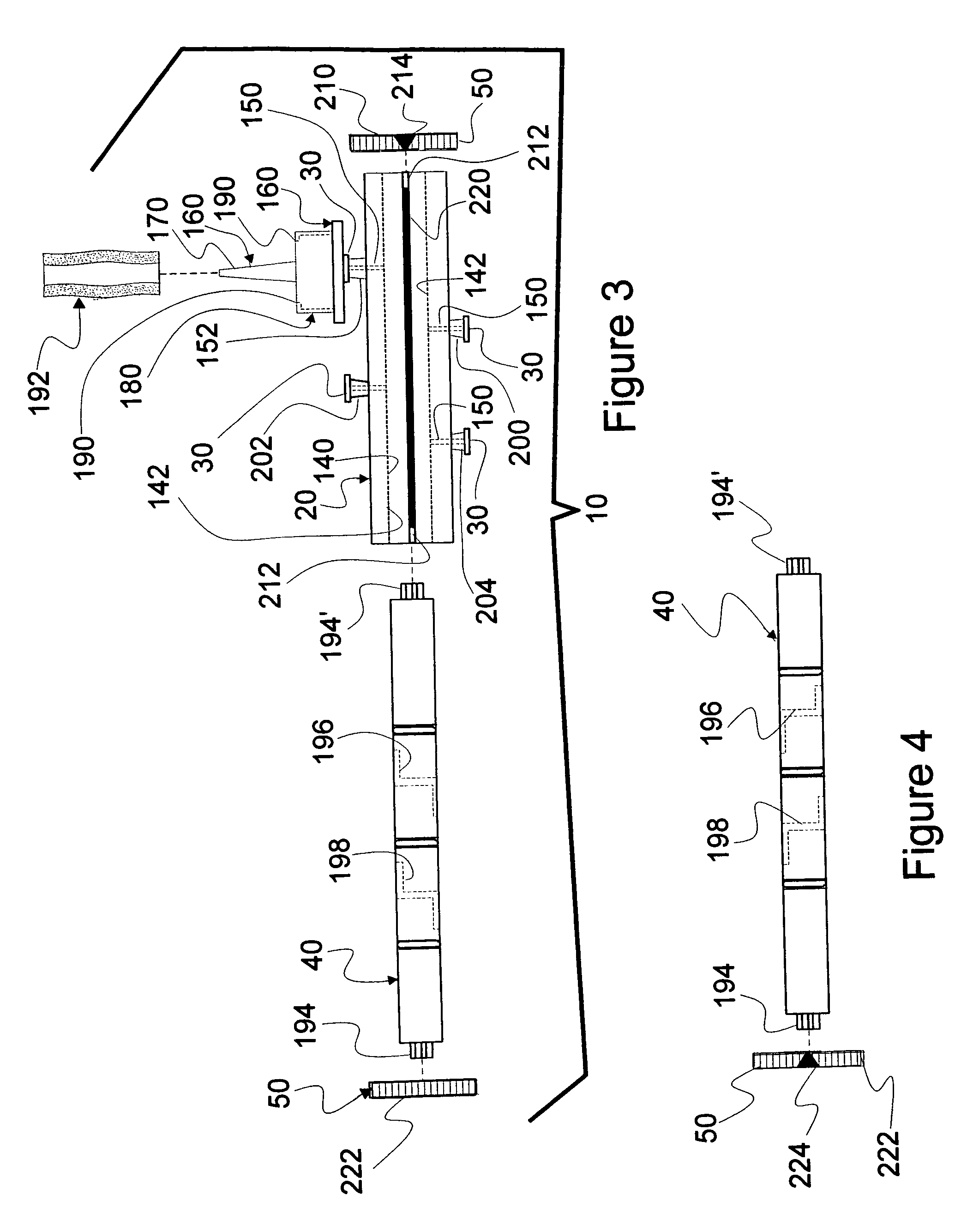
[0088]A valve assembly 10 is seen in FIG. 1. Valve assembly 10 comprises an outer, hollow, cylindrical housing 20 which has a plurality of externally accessible connecting ports, generally numbered 30. Disposed within the hollow of the housing is a close fitting cylindrical rod 40. Disposed on each end of cylindrical rod 40 is a handle, generally numbered 50, by which rod 40 is captured, rotated and displaced within housing 20.

[0089]A multi-chamber-pre-flush syringe configuration 60 is seen in FIG. 2. A key part of configuration 60 is a multi-chamber syringe 70. Details of design and operational modes of a mult...


PUM


Abstract

A combination of a valve assembly and multi-chamber, sequential delivery syringe is disclosed. The combination effectively provides a safety system for transferring hazardous materials from a vial to a site of use. All potentially hazardous materials are flushed from exposed connecting sites prior to disconnections.

Description

CONTINUATION-IN-PART[0001]This patent application is a Continuation-in-Part of U.S. patent application Ser. No. 11 / 359,304, entitled MIXING SYRINGE WITH AND WITHOUT FLUSH [Thorne, Jr. '304], filed on Feb. 21, 2006, and issued as U.S. Pat. No. 7,101,354; which is a Continuation-in-Part of U.S. patent application Ser. No. 11 / 284,504, entitled MULTI-CHAMBER, SEQUENTIAL DOSE DISPENSING SYRINGE [Thorne, Jr. '504], filed on Nov. 22, 2005, and issued as U.S. Pat. No. 7,048,720; which is a Continuation-in-Part of U.S. patent application Ser. No. 10 / 838,101, entitled MULTI-CHAMBER, SEQUENTIAL DOSE DISPENSING SYRINGE [Howlett], filed on May 3, 2004, and issued as U.S. Pat. No. 6,997,910; all of which are incorporated herein by reference in their entireties.FIELD OF INVENTION[0002]This invention is related to safety dispensing systems and, in particular, to dispensing systems which are used to transfer those vial-transported-medicines, which, by their very nature, are considered caustic and da...

Claims


Application Information

Patent Timeline
Patent Type & Authority Patents(United States)
IPC IPC(8): A61M1/00A61M5/00
CPCA61J1/2096A61J2001/201A61J2001/2058A61J2001/2062A61J2001/2075A61J2001/2082A61M2039/224A61J1/201A61J1/2058A61J1/2062A61J1/2075A61J1/2082
Inventor THORNE, JR., GALE H.THORNE, GALE H.
Owner INFUSIVE TECH LLC
Why Eureka
Try Eureka