
Fingerprint detection device and method and associated touch control device with fingerprint detection

Active Publication Date: 2010-04-22
ACER INC
View PDF14 Cites 27 Cited by
  • Summary
  • Abstract
  • Description
  • Claims
  • Application Information

AI Technical Summary

Benefits of technology

[0007]It is therefore one objective of the present invention to provide a capacitive fingerprint detection device and method which employs specially designed detecting units to simplify hardware circuits and to avoid the mutual interference between neighboring detecting units and the interference of external static electricity, thereby upgrading the accuracy of fingerprint detection.

Problems solved by technology

However, this approach has limitation on the speed of sweeping the finger and the force of pressing the detecting area, and also encounters the problems resulted from uneven touch and image recombination.

Method used


Image

  • Fingerprint detection device and method and associated touch control device with fingerprint detection
  • Fingerprint detection device and method and associated touch control device with fingerprint detection
  • Fingerprint detection device and method and associated touch control device with fingerprint detection

Examples


Embodiment Construction

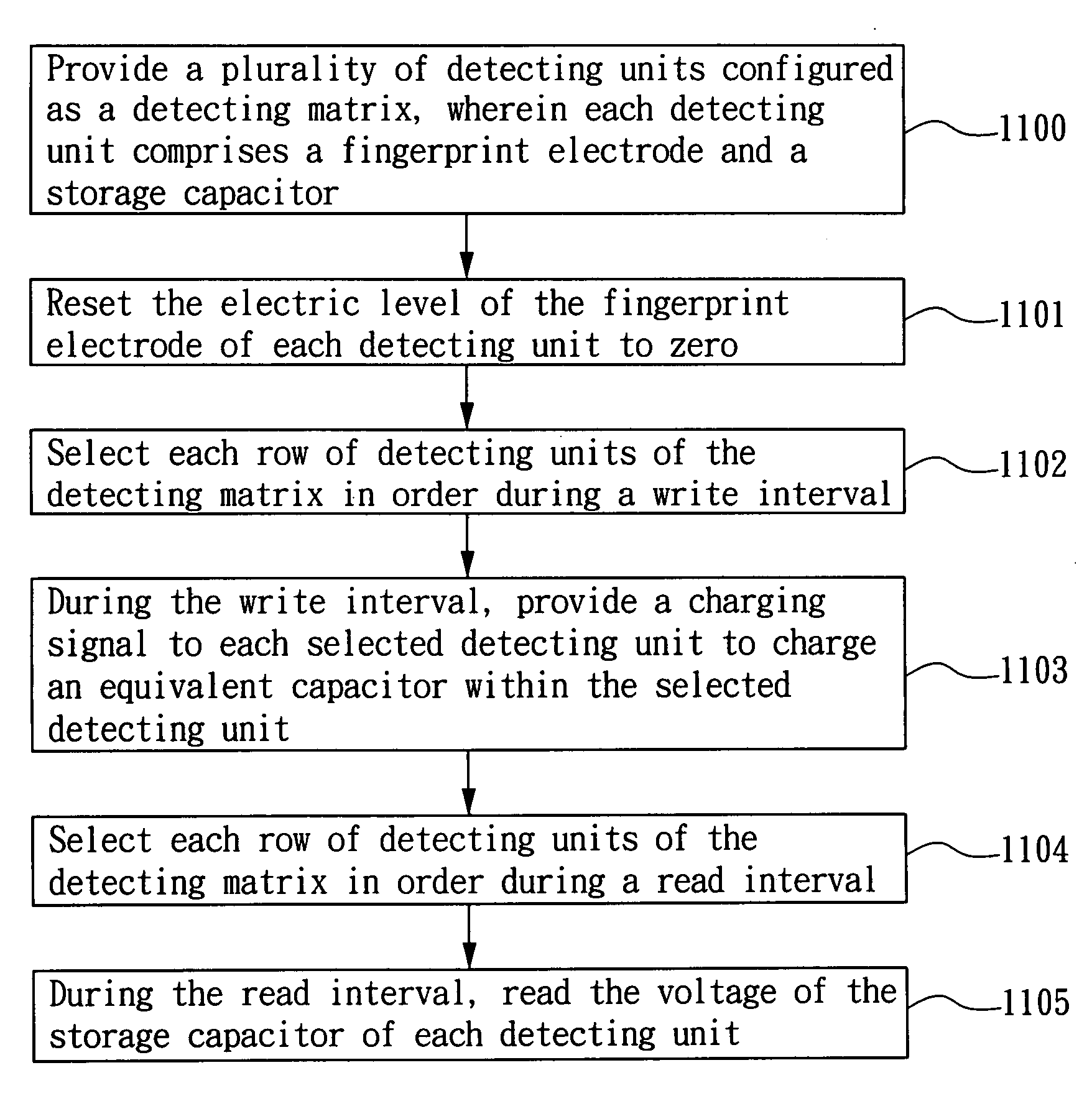
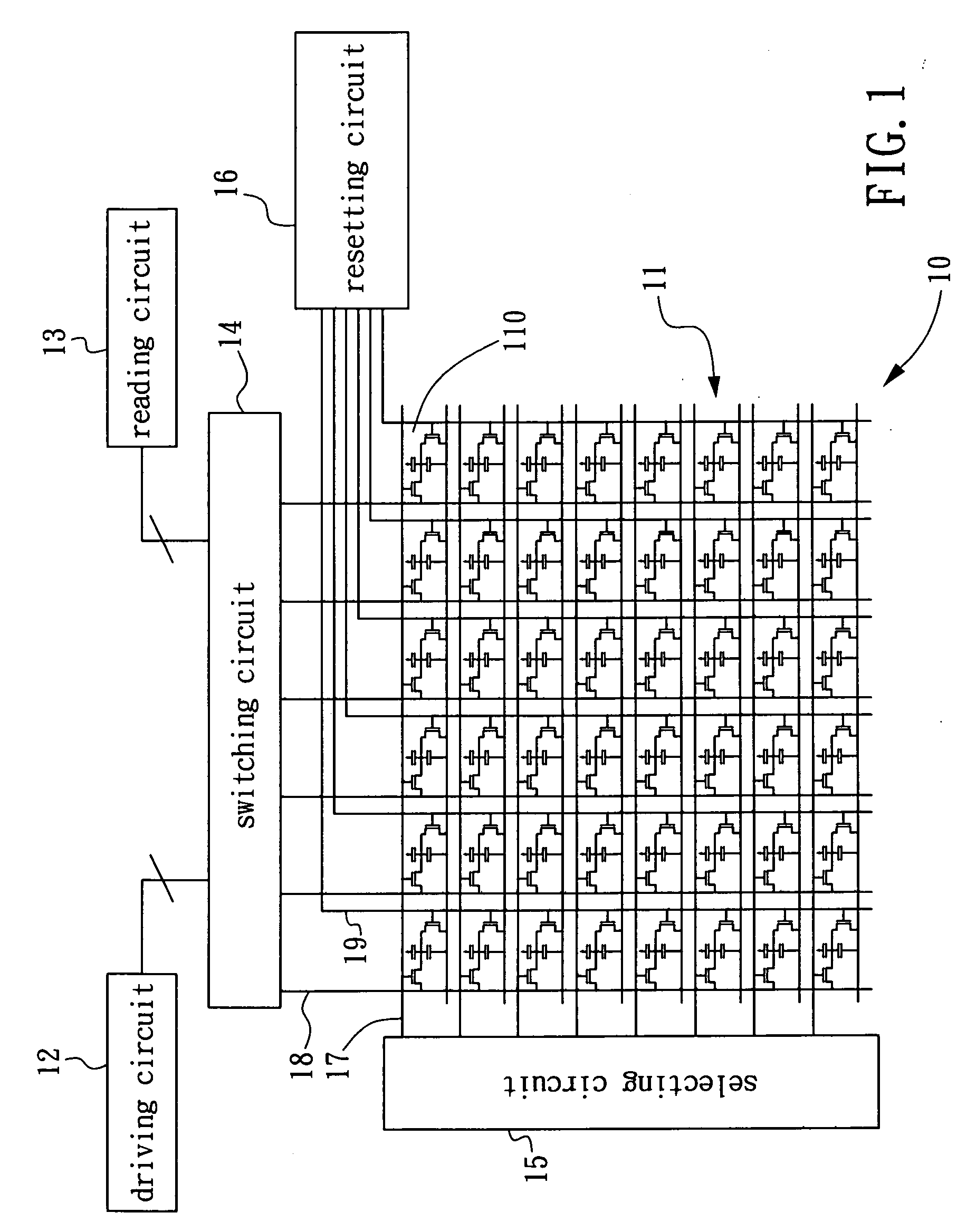
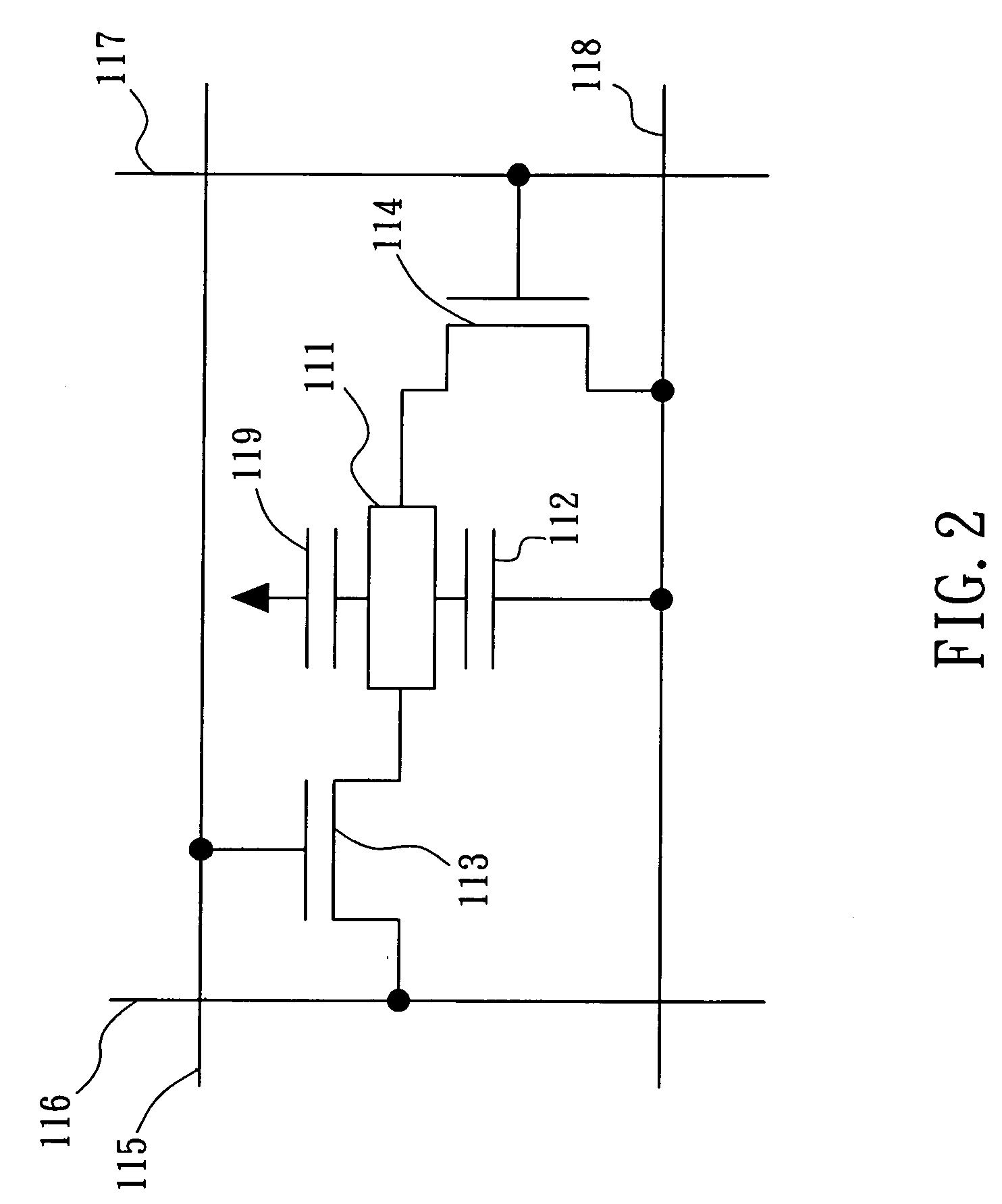
[0023]FIG. 1 is a block diagram of the first preferred embodiment of the capacitive fingerprint detection device according to the present invention, wherein the fingerprint detection device 10 includes a detecting matrix 11, a driving circuit 12, a reading circuit 13, a switching circuit 14, a selecting circuit 15 and a resetting circuit 16. The detecting matrix 11 includes a plurality of detecting units 110 which are configured as a plurality of horizontal rows and vertical columns (In FIG. 1, the detecting matrix 11 is shown as, but not limited to, eight rows and six columns). The selecting circuit 15 is coupled to the detecting matrix 11 via a plurality of control lines 17, and each control line 17 is coupled to one row of detecting units 110. The switching circuit 14 is coupled to the detecting matrix 11 via a plurality of data lines 18, and each data line 18 is coupled to one column of detecting units 110. The driving circuit 12 and the reading circuit 13 is respectively couple...


PUM


Abstract

A fingerprint detection device and method and an associated touch control device with fingerprint detection are disclosed. The fingerprint detection device includes special detecting units for upgrading the accuracy of fingerprint detection. The fingerprint detection device comprises a plurality of detecting units, a driving circuit and a reading circuit. Each detecting unit includes a fingerprint electrode and a storage capacitor coupled to the fingerprint electrode. A sense capacitor can be formed between the fingerprint electrode and a finger, where the sense capacitor is parallel connected to the storage capacitor. The driving circuit is coupled to the detecting units and provides a charging signal to charge an equivalent capacitor of each detecting unit, where the capacitance of the equivalent capacitor is determined according to whether the sense capacitor is formed within the detecting unit. The reading circuit is coupled to the detecting units and reads the voltage of the storage capacitor after the equivalent capacitor is charged, so as to determine whether the detecting unit detects a portion of fingerprint and the detected portion is a furrow or ridge.

Description

BACKGROUND OF INVENTION[0001]1. Field of the Invention[0002]The present invention relates to fingerprint detection, and more particularly to a fingerprint detection device and method and an associated touch control device with fingerprint detection.[0003]2. Description of the Prior Art[0004]Fingerprint detection is one of the most popular biometrics for identity recognition now. Since each person's fingerprint is different, the true identity of a person can be recognized by performing fingerprint detection on him. Fingerprint detection has various advantages in identity recognition, and thus many electronic products have integrated the function of fingerprint detection, such as the notebooks, cellular phones, portable disks, etc.[0005]In order to effectively perform fingerprint detection, the design of a fingerprint detector is a key factor. The detecting area of a traditional fingerprint detector is designed in a strip shape. When a person performs fingerprint detection, he needs t...

Claims


Application Information

Patent Timeline
IPC IPC(8): G06K9/00
CPCG06K9/0002G06V40/1306
Inventor CHEN, CHIH-CHIANG
Owner ACER INC
Learn More