Radio communications apparatus and transmission power control method thereof

a radio communication apparatus and control method technology, applied in the direction of power management, gain control, wireless communication, etc., can solve the problems of reducing portability, increasing circuit scale and power consumption, and reducing so as to ensure the accuracy of transmit power control, ensure the effect of reducing power consumption and small apparatus siz

Inactive Publication Date: 2007-12-18
PANASONIC CORP
View PDF9 Cites 2 Cited by
  • Summary
  • Abstract
  • Description
  • Claims
  • Application Information

AI Technical Summary

Benefits of technology

[0031]According to the invention, via a configuration for respectively controlling digital-to-analog conversion means provided in the preliminary stage of a modulator for frequency-converting a transmission signal to a signal in the IF band, the means generating an analog baseband signal to be supplied to the modulator, and a plurality of variable power amplification means for variably amplifying the transmission signal modulated by the modulator, it is possible to upgrade the accuracy of transmit power control and assure lower power consumption and smaller size of apparatus via a simple configuration

Problems solved by technology

This results in the fact that a signal from another station acts as an interference wave and degrades the circuit quality of a local station.
However, an attempt to perform variable power amplification control using a high-accuracy variable power amplifier results in an increased circuit scale and power consumption as well as reduced portability.

Method used


Image

  • Radio communications apparatus and transmission power control method thereof
  • Radio communications apparatus and transmission power control method thereof
  • Radio communications apparatus and transmission power control method thereof

Examples


embodiment 1

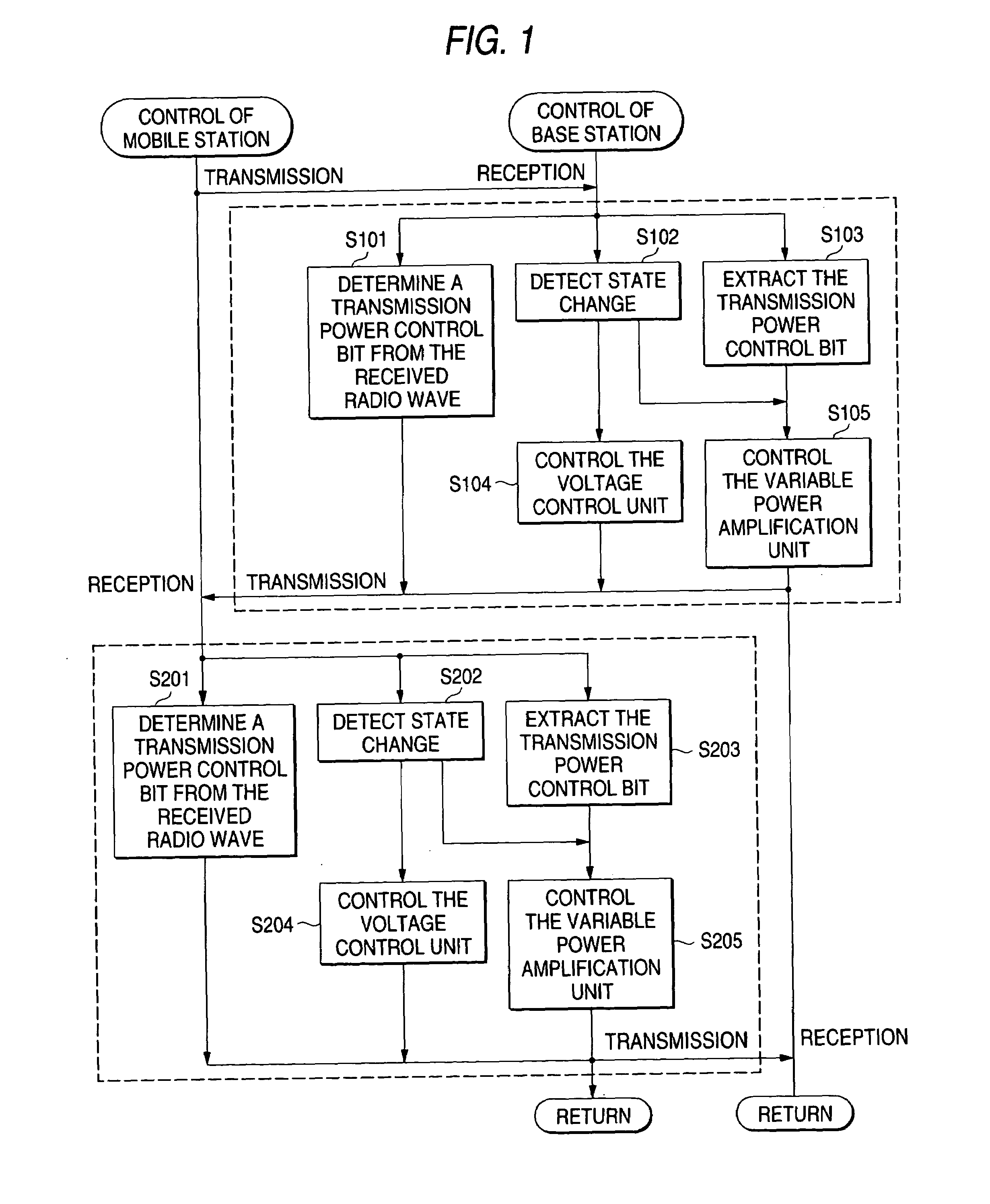
[0045]FIG. 1 is a flowchart showing the procedure of the transmission power control method according to first embodiment of the invention. As shown in FIG. 1, in case a base station and a mobile station communicates with each other, the base station determines a transmission power bit from a radio wave received from the mobile station (S101), inserts the transmission power control bit in a transmission signal, and transmits the resulting signal to the mobile station. The mobile station receives the signal transmitted from the base station, extracts the transmission power bit (S203) and controls its variable power amplification unit according to the transmission power control bit and the states of the local station and the distant station detected in Step 202 (S205).

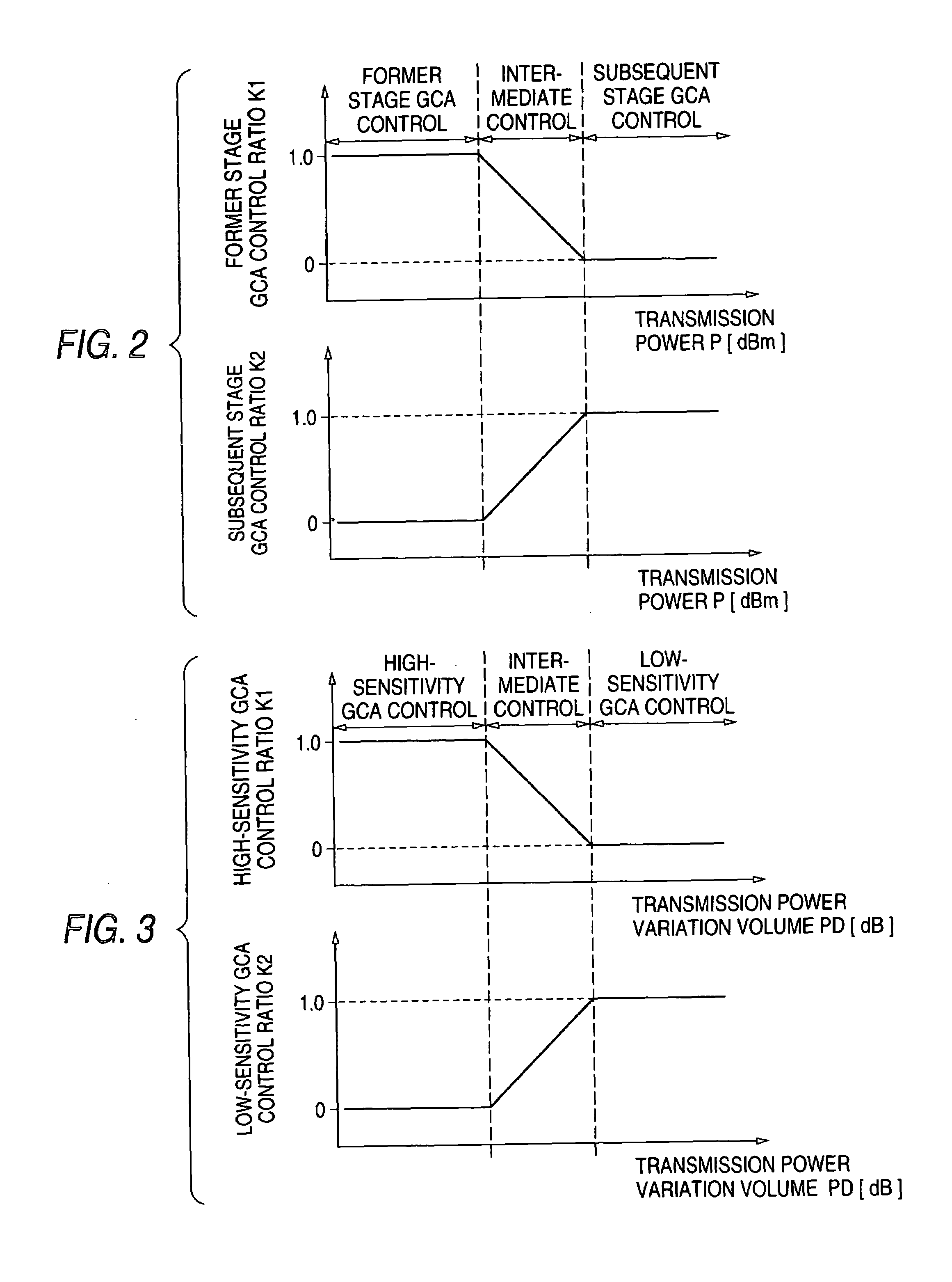
[0046]In Step S205, the mobile station can modify the control ratio of the variable power amplification unit according to the states of the local station and the distant station. For example, the mobile station detects th...

embodiment 2

[0065]FIG. 1 is a flowchart showing the procedure of the transmission power control method according to second embodiment of the invention. As shown in FIG. 1, in case a base station and a mobile station communicates with each other, the base station determines a transmission power bit from a radio wave received from the mobile station (S101), inserts the transmission power control bit in a transmission signal, and transmits the resulting signal to the mobile station. The mobile station receives the signal transmitted from the base station, extracts the transmission power bit (S203) and controls its variable power amplification unit according to the transmission power control bit and the states of the local station and the distant station detected in Step 202 (S204).

[0066]In Step S204, the mobile station can modify the control ratio of voltage control unit according to the states of the local station and the distant station. For example, the mobile station detects the absolute value...

embodiment 3

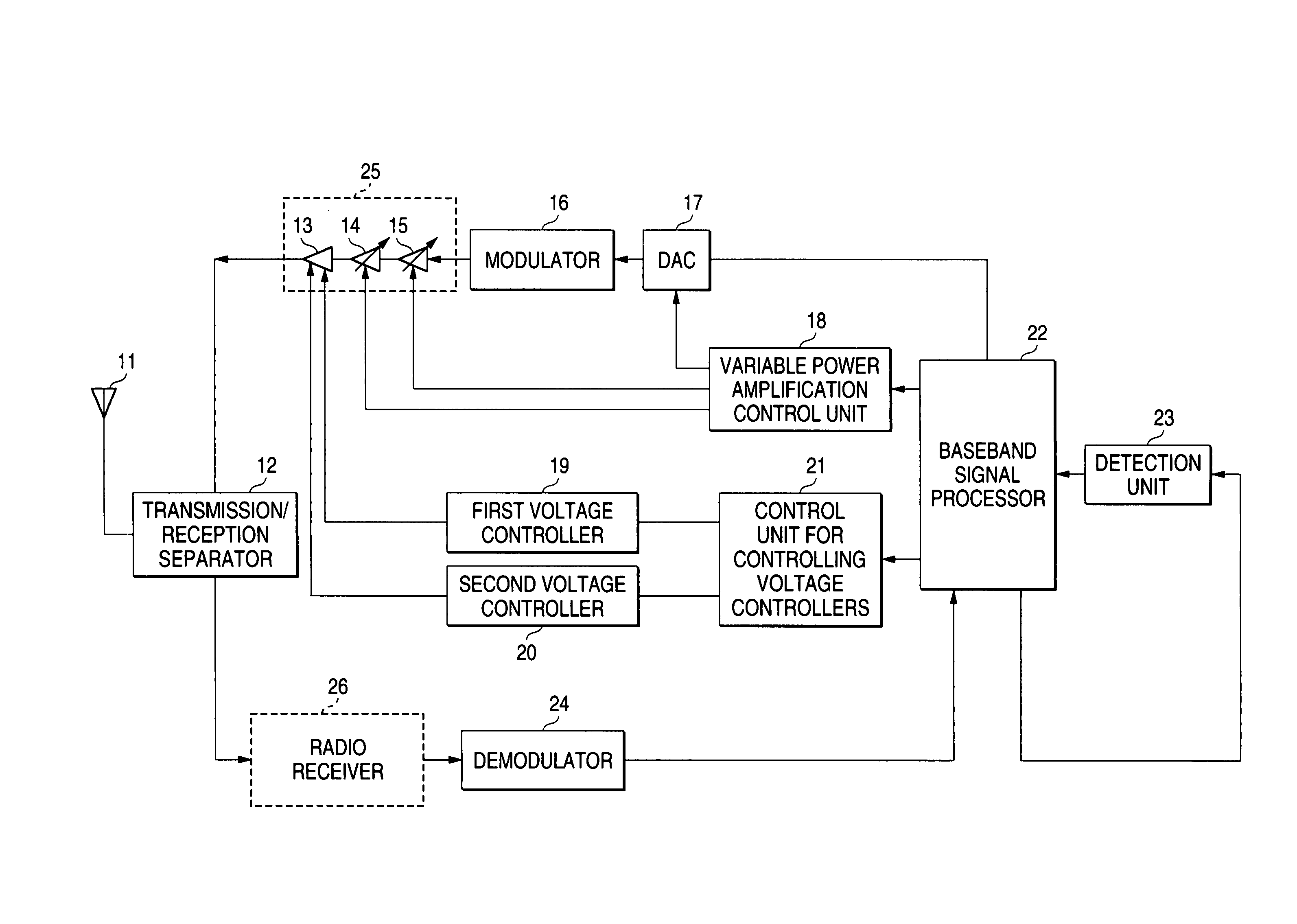
[0082]FIG. 11 is a block diagram showing an embodiment of radio communications apparatus according to the invention. In FIG. 11, the numeral 11 represents an antenna, 12 a transmit / receive separator, 13 a power amplifier, 14 a first variable power amplifier, 15 a second variable power amplifier, 16 a modulator, 17 a digital-to-analog converter (DAC), 18 variable power amplification control unit, 19 first voltage controller, 20 second voltage controller, 21 control unit for controlling voltage controllers, 11 a baseband signal processor, 23 state detection unit, 24 a demodulator, 25 a radio transmitter, and 26 a radio receiver.

[0083]In case the radio communications apparatus shown in FIG. 11, the baseband signal processor 22 determines a transmission power bit received from the base station and inserts the transmission power control bit in a transmission signal. The transmit signal is converted to an analog signal by the DAC 17, frequency-converted to a signal in the IF band by the m...


PUM


Abstract

Radio communications apparatus according to the invention comprises a DAC, a variable power amplification unit including at least two variable power amplifiers, and variable power amplification control unit for controlling the variable power amplifiers. The variable power amplification control unit controls the variable power amplifiers in order to upgrade the accuracy of the apparatus and assures a smaller apparatus design.

Description

BACKGROUND OF THE INVENTION[0001]The present invention relates to a transmission power control method and radio communications apparatus effective for control of transmission power in the cellular CDMA (Code Division Multiple Access) system.[0002]In the CDMA system, a single frequency band is shared by a plurality of users. This results in the fact that a signal from another station acts as an interference wave and degrades the circuit quality of a local station. As a technology to solve this problem, transmission power control is used. Particularly, As a transmission power control method for following an interference signal that varies instantaneously, a transmission power control method via closed loop is known.[0003]FIG. 12 shows an example of a conventional transmission power control method via closed loop. As shown in FIG. 12, in case a base station and a mobile station communicates with each other, the base station determines a transmission power bit from a radio wave received...

Claims


Application Information

Patent Timeline
Patent Type & Authority Patents(United States)
IPC IPC(8): H01Q11/12H04B1/04H03G3/20H04B7/005H04B7/26
CPCH04W52/52H04W52/36
Inventor ICHIKAWA, YASUFUMI
Owner PANASONIC CORP
Why Eureka
Try Eureka