
Method and Apparatus for Determining 3D Shapes of Objects

a technology of object shape and 3d shape, applied in the field of acquiring images of objects, can solve the problems of poor quality models, high sensitive visual hulls to camera calibration errors,

Inactive Publication Date: 2010-04-22
MITSUBISHI ELECTRIC RES LAB INC
View PDF44 Cites 14 Cited by
  • Summary
  • Abstract
  • Description
  • Claims
  • Application Information

AI Technical Summary

Benefits of technology

The patent describes a way to determine the shape of an object in a scene using multiple light sources. By analyzing the silhouettes of the object, the method creates a visual hull that approximates the object's shape. This can be useful in various applications such as in autonomous vehicles for obstacle detection or in augmented reality for creating virtual objects in real-life scenarios.

Problems solved by technology

However, visual hulls are highly-sensitive to camera calibration errors.
This sensitivity becomes increasingly apparent as the number of images increases, resulting in poor-quality models.

Method used


Image

  • Method and Apparatus for Determining 3D Shapes of Objects
  • Method and Apparatus for Determining 3D Shapes of Objects
  • Method and Apparatus for Determining 3D Shapes of Objects

Examples


Embodiment Construction

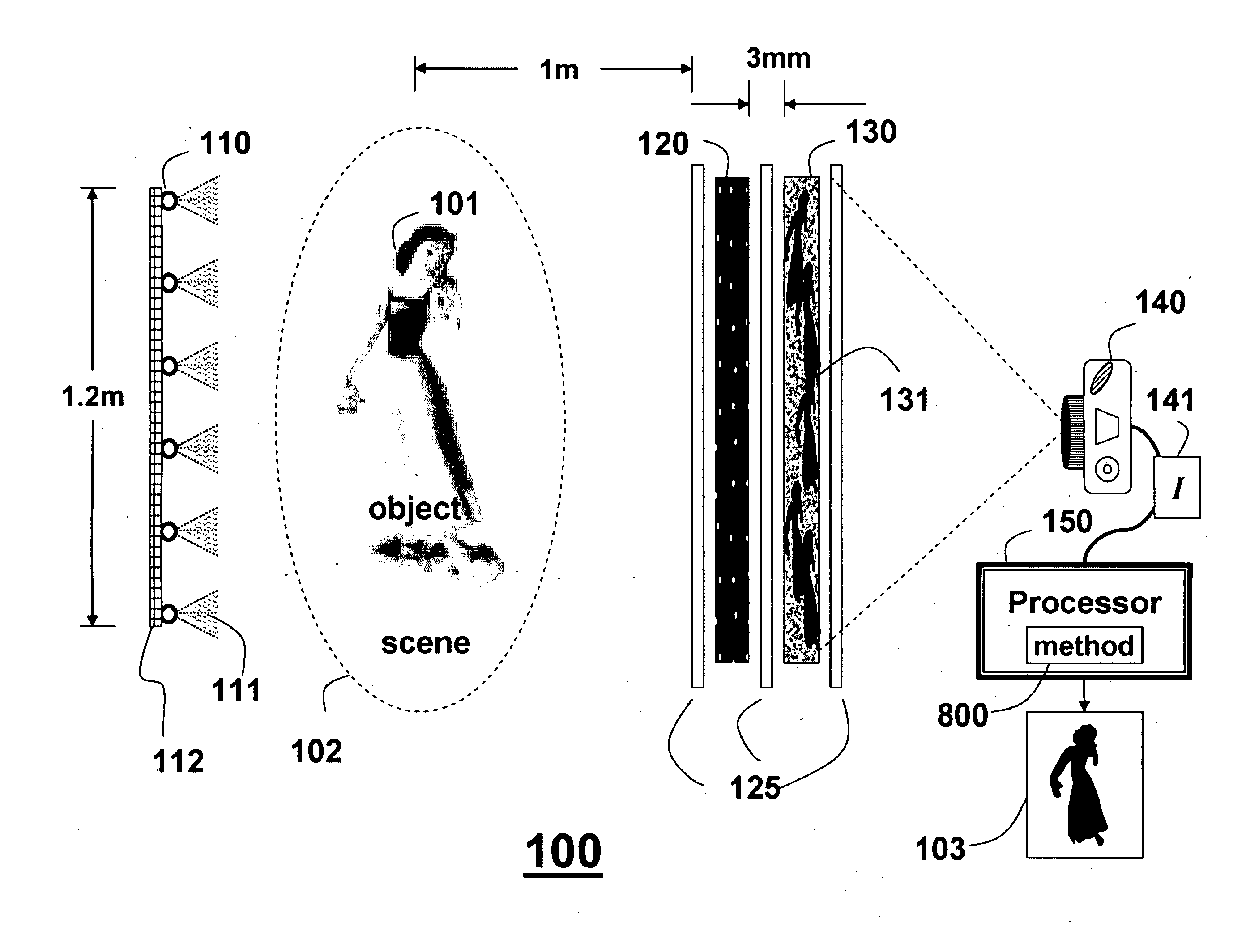
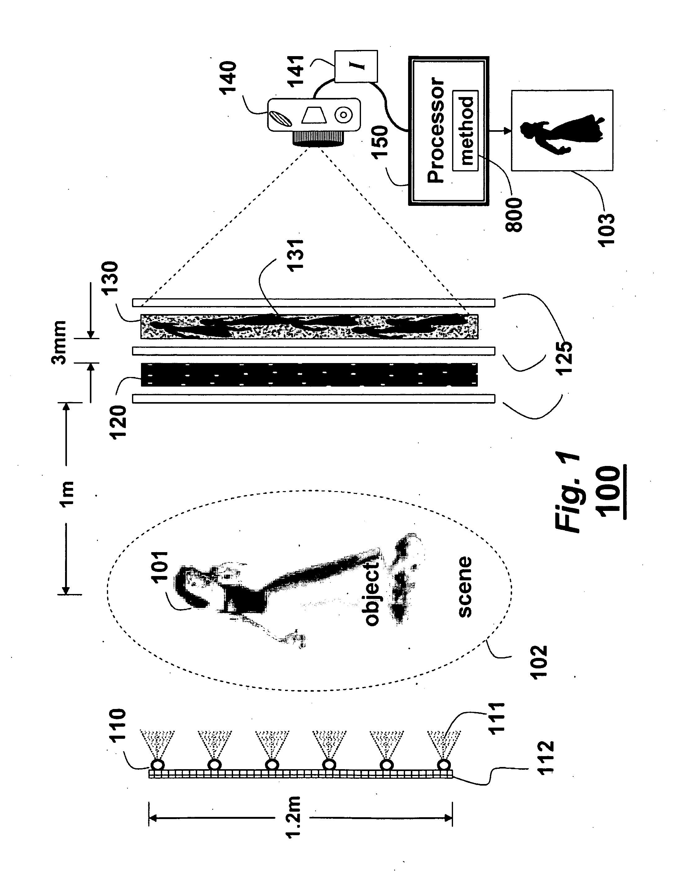
[0020]FIG. 1 schematically shows a shield field camera system 100 for determining a 3D shape 103 of an object 101 in a scene 102 according to embodiments of our invention. A visual hull constructed from the single image approximates the 3D shape of the object.

[0021]As defined herein, the visual hull 103 is a geometric model generated by our shape-from-silhouette 3D reconstruction method 800, see FIG. 8. The silhouette is the 2D projection or shadow of the 3D object onto an image plane. The image can be segmented into a foreground and background binary image. The foreground or silhouette is the 2D projection of the corresponding 3D foreground object. Along with the camera viewing parameters, the silhouette defines a back-projected generalized cone that contains the actual object.

[0022]The system includes an illumination source 110, an attenuating mask 120, a diffuser screen 130, and a sensor 140.

[0023]The illumination source 110 can be a large light box or a set of point light source...


PUM


Abstract

An apparatus and method determine a 3D shape of an object in a scene. The object is illuminated to cast multiple silhouettes on a diffusing screen coplanar and in close proximity to a mask. A single image acquired of the diffusing screen is partitioned into subview according to the silhouettes. A visual hull of the object is then constructed according to isosurfaces of the binary images to approximate the 3D shape of the object.

Description

FIELD OF THE INVENTION[0001]This invention relates generally to acquiring images of objects, and more particularly to determining a 3D shape of an object from a single image.BACKGROUND OF THE INVENTION[0002]Light Fields[0003]A light field is a function that describes light traveling in every direction through every point in a space. The light field can be acquired by a pinhole camera array, prisms and lenses, a plentopic camera with a lenslet array, or a heterodyne camera, where the lenslet array is replaced by an attenuating mask.[0004]Coded-Aperture Imaging[0005]In astronomical and medical imaging, a coded aperture is used to acquire x-rays and gamma rays. High-frequency attenuating patterns can separate the effects of global and direct illumination, estimate intensity and depth from defocused images, and minimize effects of glare.[0006]Silhouettes[0007]When an object in a scene is illuminated by a point light source, the shadow that is cast forms an outline or silhouette of the o...

Claims


Application Information

Patent Timeline
Patent Type & Authority Applications(United States)
IPC IPC(8): G06K9/00F21V11/00
CPCG01B11/2513G06T2207/20056G06T2207/10152G06T7/0057G06T7/521G06T7/557
Inventor AGRAWAL, AMIT K.RASKAR, RAMESHLANMAN, DOUGLAS ROBERTTAUBIN, GABRIEL
Owner MITSUBISHI ELECTRIC RES LAB INC
Learn More