Synchronization transport over passive optical networks

a technology of optical network and synchronization, applied in the field of passive optical network, can solve the problems of high cost of tdm circuit, inability of most deployed base stations to separate voice/data traffic, and inability to ignore service providers' demand for tdm, etc., and achieve the effect of facilitating transpor

Active Publication Date: 2010-04-22
AVAGO TECH INT SALES PTE LTD
View PDF21 Cites 70 Cited by
  • Summary
  • Abstract
  • Description
  • Claims
  • Application Information

AI Technical Summary

Benefits of technology

[0009]One embodiment provides an Ethernet Passive Optical Network (EPON) system for clock transport. The system includes a reference clock configured to generate a frequency-reference signal, an optical line terminal (OLT) coupled to the reference clock, and an optical network unit (ONU). The OLT includes a clock generator configured to generate an OLT and EPON transceiver clock synchronized with the frequency-reference signal. The ONU includes an optical transceiver, a clock recovery module, and a clock output mechanism. The optical transceiver is configured to transmit optical signals to and receive optical signals from the OLT. The clock-recovery module is configured to recover the frequency-reference signal from the received optical signals. The clock output mechanism is configured to output the recovered frequency-reference signal, thus facilitating transport of the frequency-reference signal over the EPON.

Problems solved by technology

Although IP is already pervasive throughout the telecommunications industry, demand for TDM cannot be ignored by service providers.
However, these TDM circuits are quite expensive.
However, most deployed base stations have no capability of separating voice / data traffic to support such an approach.

Method used


Image

  • Synchronization transport over passive optical networks
  • Synchronization transport over passive optical networks
  • Synchronization transport over passive optical networks

Examples


Embodiment Construction

[0025]The following description is presented to enable any person skilled in the art to make and use the embodiments, and is provided in the context of a particular application and its requirements. Various modifications to the disclosed embodiments will be readily apparent to those skilled in the art, and the general principles defined herein may be applied to other embodiments and applications without departing from the spirit and scope of the present disclosure. Thus, the present invention is not limited to the embodiments shown, but is to be accorded the widest scope consistent with the principles and features disclosed herein.

Overview

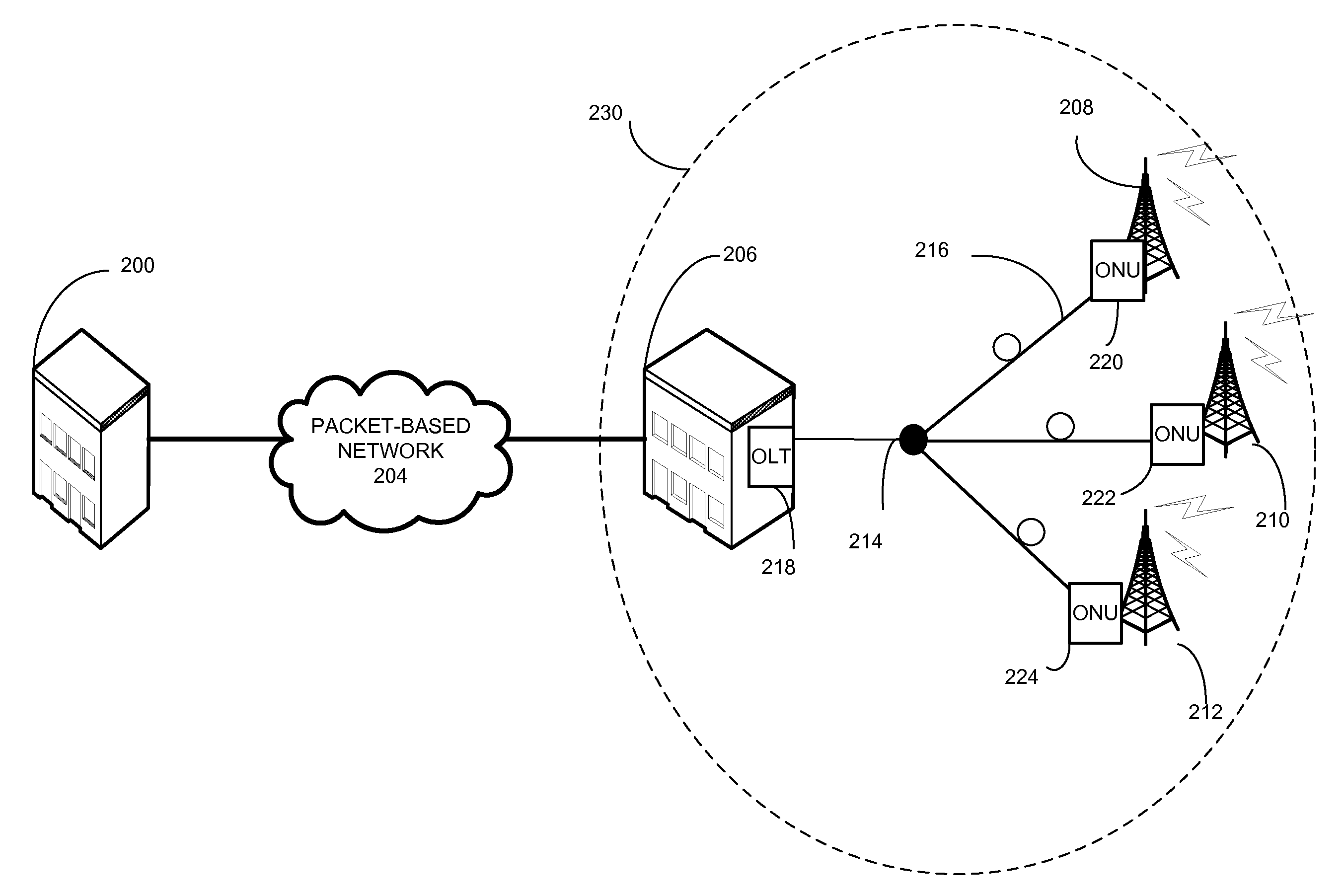
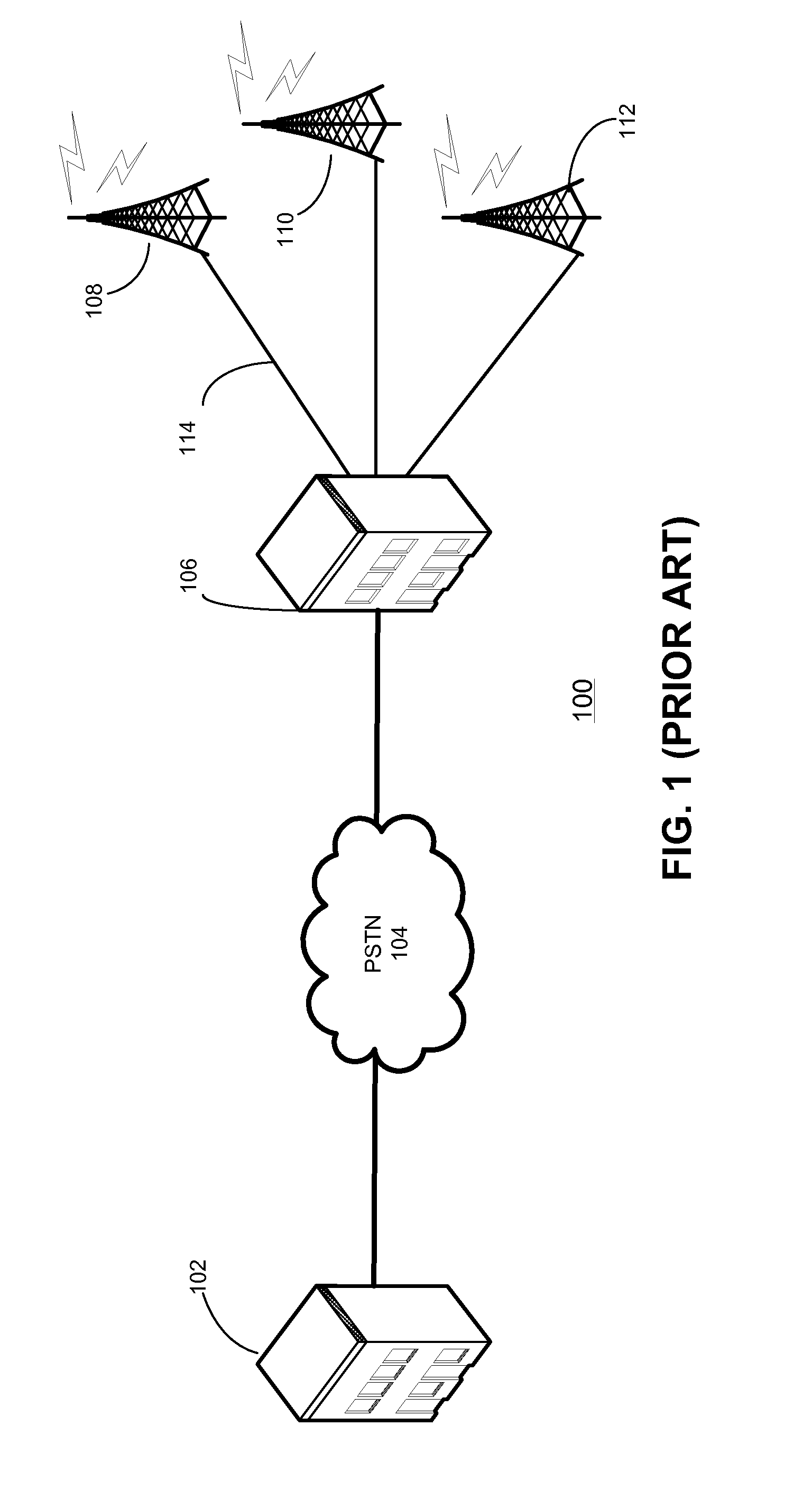
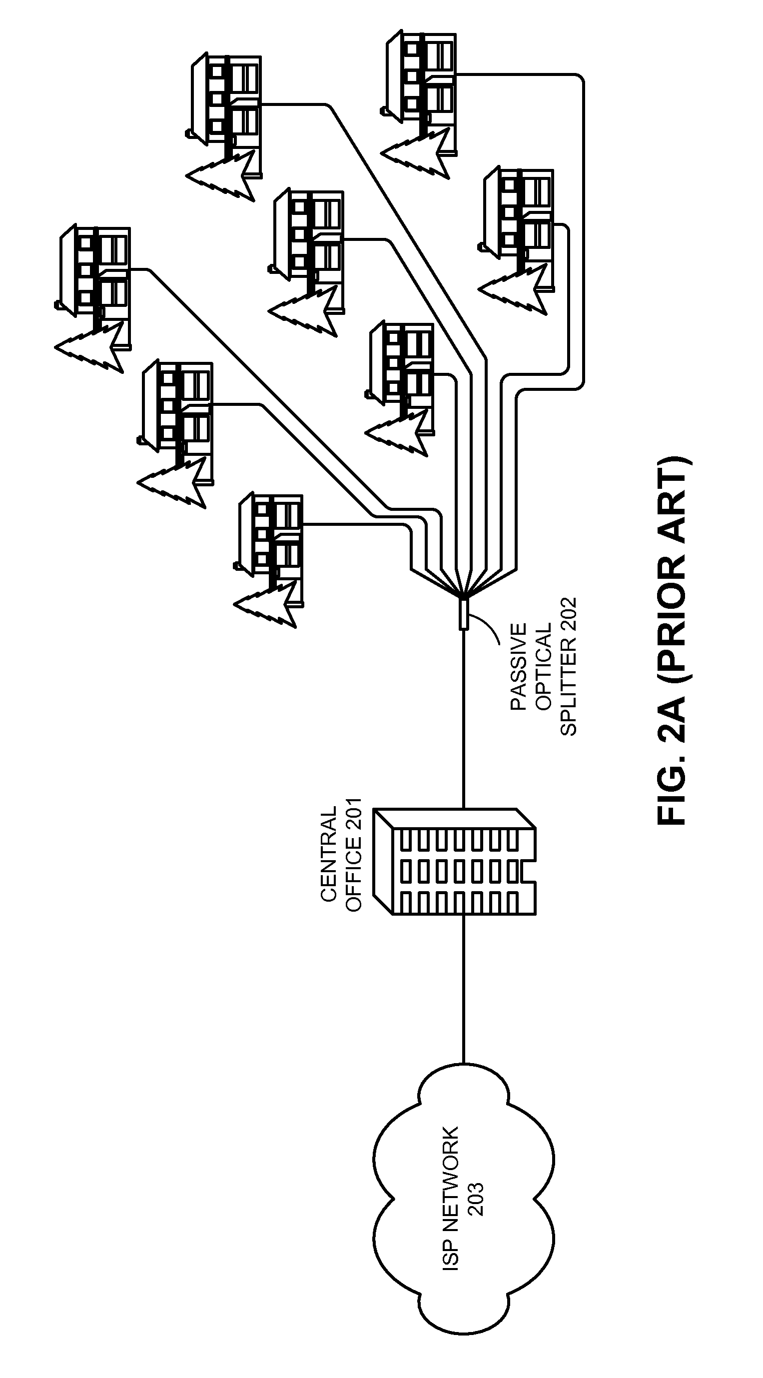
[0026]Embodiments of the present invention provide a system that can transport a frequency- and phase-synchronized clock over an Ethernet PON (EPON). A TDM network (especially a cellular / mobile network) is circuit based and requires a synchronous central clock throughout the entire system. However, an EPON is packet based and does not facilitate a ...


PUM


Abstract

One embodiment provides an Ethernet Passive Optical Network (EPON) system for clock transport. The system includes a reference clock configured to generate a frequency-reference signal, an optical line terminal (OLT) coupled to the reference clock, and an optical network unit (ONU). The OLT includes a clock generator configured to generate an OLT clock based on at least the frequency-reference signal. The ONU includes an optical transceiver, a clock recovery module, and a clock output mechanism. The optical transceiver is configured to transmit optical signals to and receive optical signals from the OLT. The clock-recovery module is configured to recover the frequency-reference signal from the received optical signals. The clock output mechanism is configured to output the recovered frequency-reference signal, thus facilitating transport of the frequency-reference signal over the EPON.

Description

RELATED APPLICATION[0001]This application claims the benefit of U.S. Provisional Application No. 61 / 107,256, Attorney Docket Number TEK08-1006PSP, entitled “Supporting TDM Traffic in Passive Optical Networks,” by inventor Barry C. Gray, filed 21 Oct. 2008.BACKGROUND[0002]1. Field[0003]This disclosure is generally related to a passive optical network (PON). More specifically, this disclosure is related to transporting a time-division-multiplexing (TDM) clock over a PON.[0004]2. Related Art[0005]IP (internet protocol)-based traffic and TDM-based traffic co-exist on today's networks. Although IP is already pervasive throughout the telecommunications industry, demand for TDM cannot be ignored by service providers.[0006]One driving force for such demand is the corporate-connectivity market, which provides connectivity services to businesses. Note that “Business Services” include voice as well as data, and although voice-over-IP (VoIP) is becoming more important, a significant portion of ...

Claims


Application Information

Patent Timeline
Patent Type & Authority Applications(United States)
IPC IPC(8): H04B10/00H04B10/2581
CPCH04J3/0658H04Q2011/0079H04Q11/0067H04J3/0667
Inventor BOYD, EDWARD W.SHIBUYA, HIDEHIKO
Owner AVAGO TECH INT SALES PTE LTD
Why Eureka
Try Eureka