Tibial Tray Having a Reinforcing Member

Inactive Publication Date: 2010-04-22
BIOMET MFG CORP
View PDF15 Cites 134 Cited by
  • Summary
  • Abstract
  • Description
  • Claims
  • Application Information

AI Technical Summary

Problems solved by technology

In some examples, when these degenerative changes are advanced, irreversible and unresponsive to non-operative management, it may ultimately become necessary to replace some or all of the natural knee joint with knee joint prosthetics.

Method used


Image

  • Tibial Tray Having a Reinforcing Member
  • Tibial Tray Having a Reinforcing Member
  • Tibial Tray Having a Reinforcing Member

Examples


Embodiment Construction

[0024]The following description is merely exemplary in nature and is not intended to limit the present disclosure, its application, or uses.

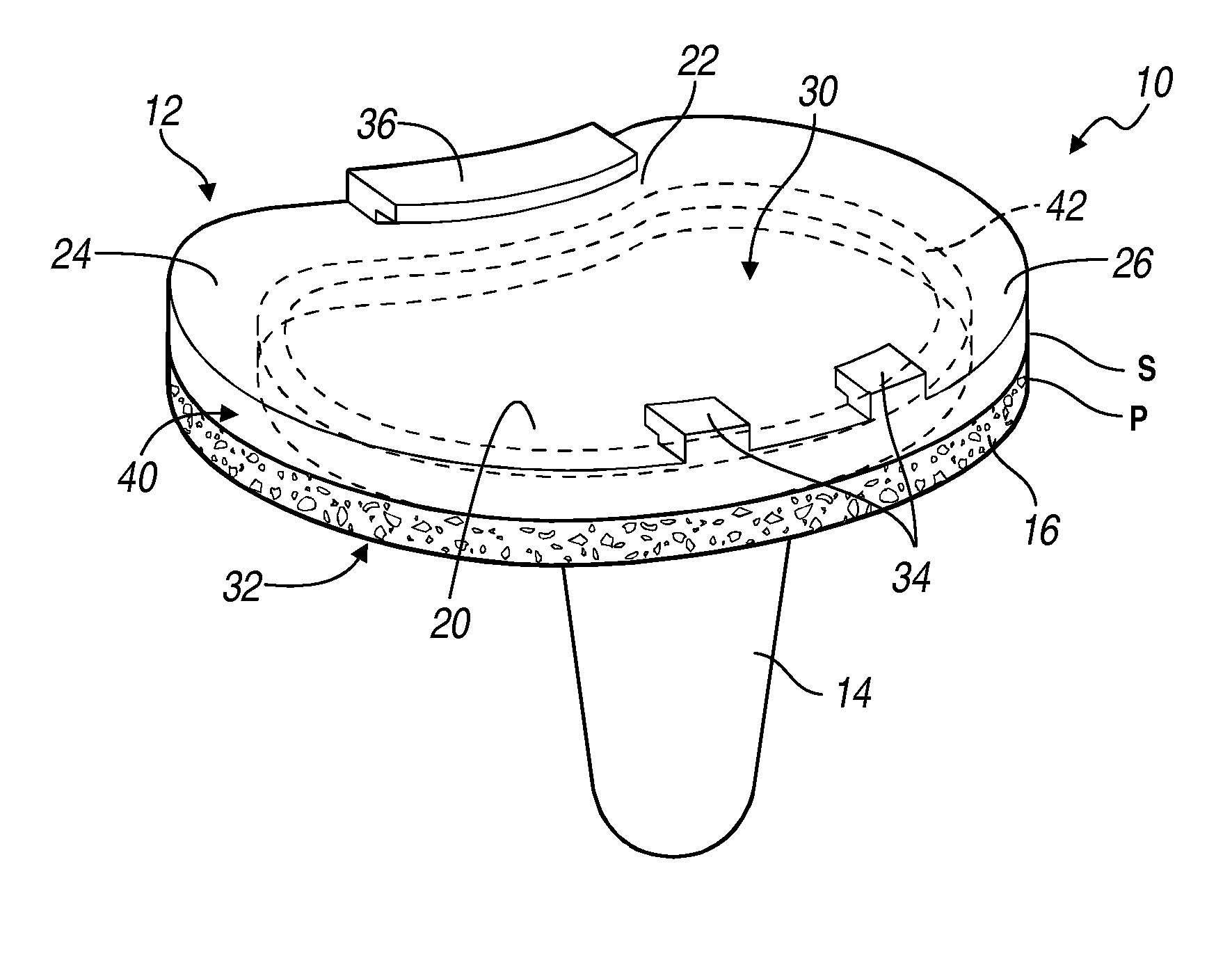
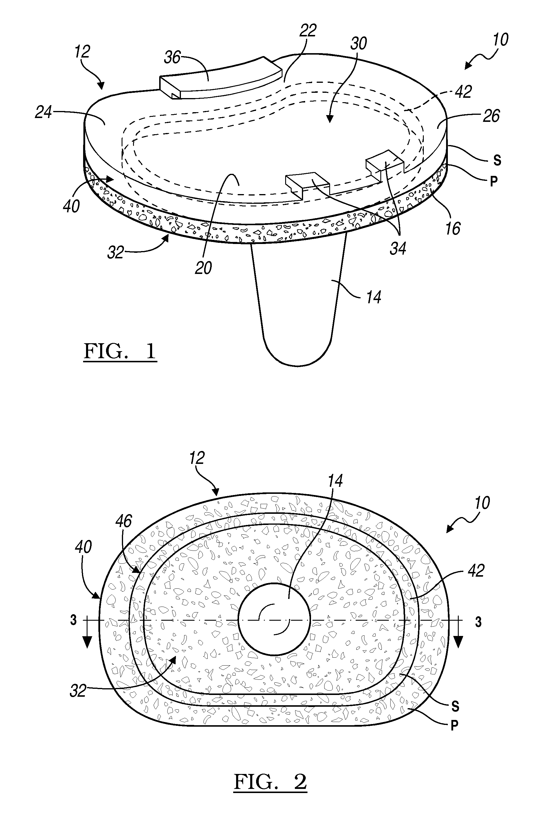
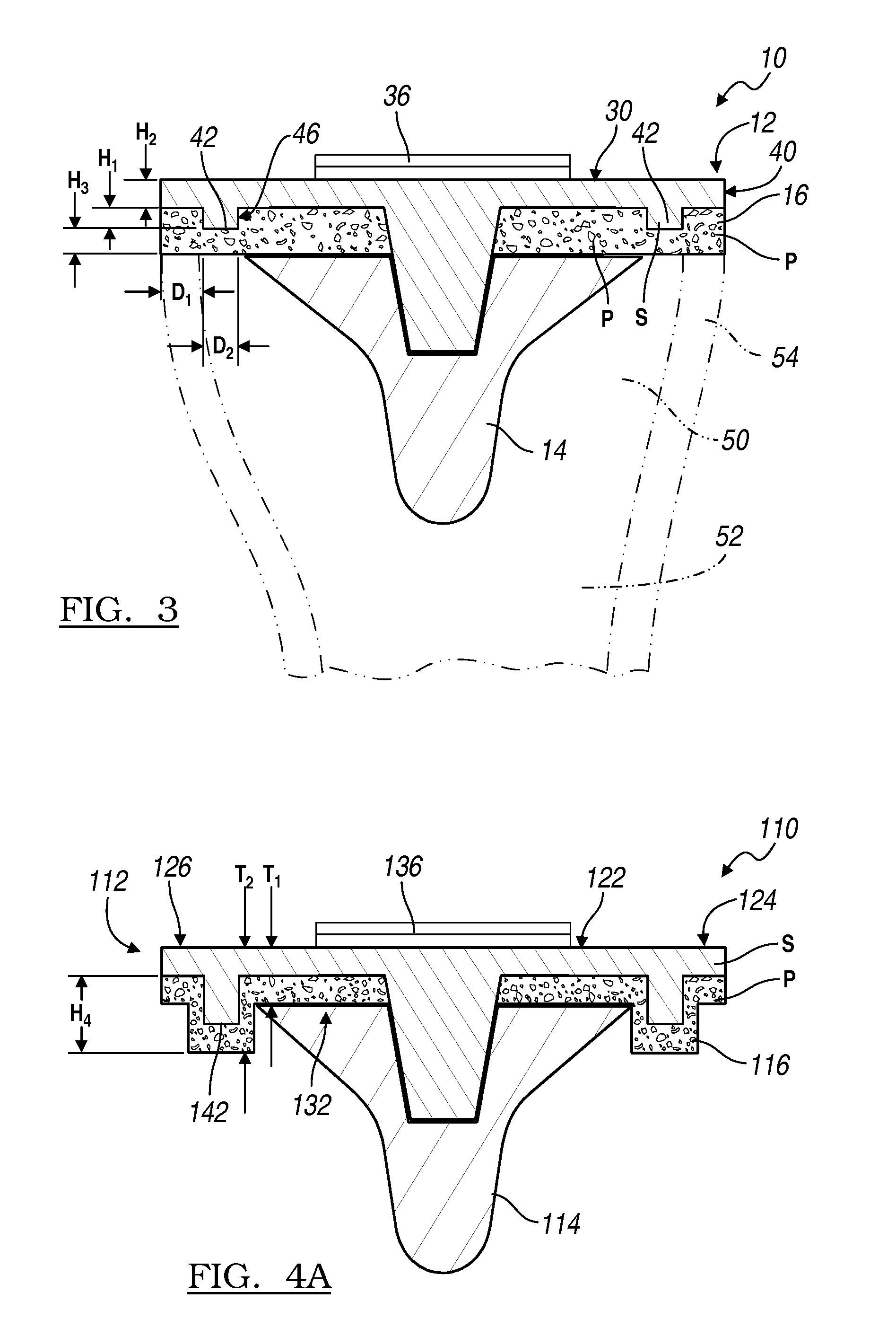
[0025]With initial reference now to FIG. 1, a tibial component constructed according to the present teachings is shown and generally identified at reference numeral 10. The tibial component 10 can generally includes a substantially planar platform-like tray 12 having a modular, inferiorly extending tibial stem 14. In other examples, the stem 14 can be integrally formed with the tibial tray 12. The tibial stem 14 can be adapted to be received in a corresponding opening made by a surgeon in a proximal tibia. The tibial component 10 according to the present teachings incorporates porous material 16 at selected areas as will be described. As will become appreciated from the following discussion, the tibial component 10 constructed in accordance to the present teachings can increase a fatigue strength of the tibial tray 12 while simultaneously maximi...


PUM


Abstract

A knee joint prosthesis can include a tibial component that can have a tibial tray. The tibial tray can include a platform-like tray that defines a superior surface and an inferior surface. The platform-like tray can have a tray perimeter and a raised wall formed on the inferior surface. The raised wall can be offset inboard relative to the tray perimeter. Porous material can be disposed on the inferior surface of the platform-like tray at a location generally between the raised wall and the tray perimeter.

Description

CROSS-REFERENCE TO RELATED APPLICATIONS[0001]This application is a continuation-in-part of U.S. patent application Ser. No. 12 / 253,259 filed on Oct. 17, 2008. The entire disclosure of the above application is incorporated herein by reference.FIELD[0002]The present disclosure relates to tibial trays and more particularly to a tibial tray incorporating a reinforcing member.BACKGROUND[0003]The statements in this section merely provide background information related to the present disclosure and may not constitute prior art.[0004]In some instances, the knee joint may undergo degenerative changes due to multiple etiologies. In some examples, when these degenerative changes are advanced, irreversible and unresponsive to non-operative management, it may ultimately become necessary to replace some or all of the natural knee joint with knee joint prosthetics. In one example, a knee joint prosthesis can comprise a femoral component and a tibial component. The femoral component and the tibial ...

Claims


Application Information

Patent Timeline
Patent Type & Authority Applications(United States)
IPC IPC(8): A61F2/38A61B17/56
CPCA61F2/30767A61F2/30965A61F2/389A61F2002/30769A61F2002/30879A61F2310/00179A61F2002/30883A61F2002/30884A61F2002/3092A61F2240/001A61F2310/00023A61F2002/30881
Inventor MAY, BRIAN M.KUMAR, MUKESH
Owner BIOMET MFG CORP
Why Eureka
Try Eureka