Audio decoding device and audio decoding method

a technology of decoding device and audio decoding method, which is applied in the field of speech decoding apparatus and speech decoding method, can solve the problems of quantization noise, difficult to hear, and quantization noise, and achieve the effect of improving the subjective quality of speech signals

Active Publication Date: 2010-04-22
III HLDG 12 LLC
View PDF19 Cites 23 Cited by
  • Summary
  • Abstract
  • Description
  • Claims
  • Application Information

AI Technical Summary

Benefits of technology

[0011]According to the present invention, upon performing tilt compensation of decoded excitation signals as post processing for decoded excitation signals, by calculating coefficients for high-band emphasis processing of weighted linear pr...

Problems solved by technology

The formant emphasis filter makes the valleys in the spectrum of a speech signal steeper, and thereby provides an effect of making quantization noise, which exists in the valley portion of the spectrum, hard to hear.
The pitch emphasis post filter makes the valleys in the spectral harmonics of a speech signal steeper, and thereby provides an effect of making quantization noise, which exists in the valley portion of the harmonics, hard to hear.
This is because waveforms matching is more difficult for signal waveforms of high frequencies than signal waveforms of low frequencies.
This energy attenuation of the high-band components of a decoded signal gives to listeners an impression that the band of the decoded signal is narrowed, and this causes the degradation of subjective quality of the decoded signal.
Howeve...

Method used


Image

  • Audio decoding device and audio decoding method
  • Audio decoding device and audio decoding method
  • Audio decoding device and audio decoding method

Examples


Embodiment Construction

[0019]An embodiment of the present invention will be explained below in detail with reference to the accompanying drawings.

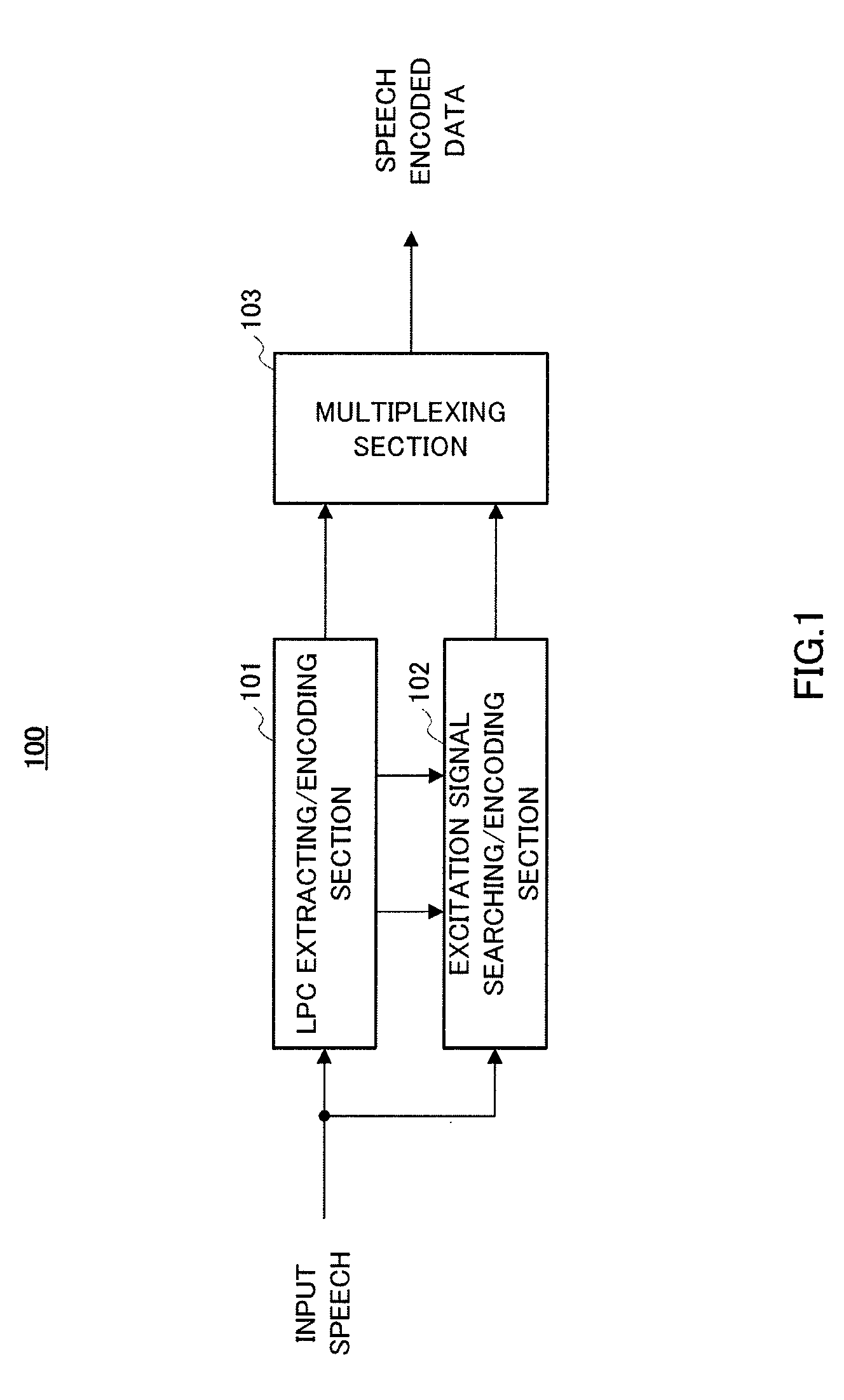
[0020]FIG. 1 is a block diagram showing the main components of speech encoding apparatus according to an embodiment of the present invention.

[0021]In FIG. 1, speech encoding apparatus 100 is provided with LPC extracting / encoding section 101, excitation signal searching / encoding section 102 and multiplexing section 103.

[0022]LPC extracting / encoding section 101 performs a linear prediction analysis of an input speech signal, to extract the linear prediction coefficients (“LPC's”) and outputs the acquired LPC's to excitation signal searching / encoding section 102. Further, LPC extracting / encoding section 101 quantizes and encodes the LPC's, and outputs the quantized LPC's to excitation signal searching / encoding section 102 and the LPC encoded data to multiplexing section 103.

[0023]Excitation signal searching / encoding section 102 performs filtering processing of the ...


PUM


Abstract

Provided is an audio decoding device which can adjust the high-range emphasis degree in accordance with a background noise level. The audio decoding device includes: a sound source signal decoding unit (204) which performs a decoding process by using sound source encoding data separated by a separation unit (201) so as to obtain a sound source signal; an LPC synthesis filter (205) which performs an LPC synthesis filtering process by using a sound source signal and an LPC generated by an LPC decoding unit (203) so as to obtain a decoded sound signal; a mode judging unit (207) which determines whether a decoded sound signal is a stationary noise section by using a decoded LSP inputted from the LPC decoding unit (203); a power calculation unit (206) which calculates the power of the decoded audio signal; an SNR calculation unit (208) which calculates an SNR of the decoded audio signal by using the power of the decoded audio signal and a mode judgment result in the mode judgment unit (207); and a post filter (209) which performs a post filtering process by using the SNR of the decoded audio signal.

Description

TECHNICAL FIELD[0001]The present invention relates to a speech decoding apparatus and speech decoding method of a CELP (Code-Excited Linear Prediction) scheme. More particularly, the present invention relates to a speech decoding apparatus and speech decoding method for compensating quantization noise in accordance with human perceptual characteristics and improving the subjective quality of decoded speech signals.BACKGROUND ART[0002]CELP type speech codec often uses a post filter to improve the subjective quality of decoded speech (for example, see Non-Patent Document 1). The post filter in Non-Patent Document 1 is based on serial connection of three filters of formant emphasis post filter, pitch emphasis post filter and spectrum tilt compensation (or high band enhancement) filter. The formant emphasis filter makes the valleys in the spectrum of a speech signal steeper, and thereby provides an effect of making quantization noise, which exists in the valley portion of the spectrum, ...

Claims


Application Information

Patent Timeline
IPC IPC(8): G10L19/00G10L21/02G10L19/14G10L19/26
CPCG10L19/26
Inventor EHARA, HIROYUKI
Owner III HLDG 12 LLC
Why Eureka
Try Eureka