Volume management system

a management system and volume technology, applied in the field of volume management system, can solve the problem of not being able to lighten the load imposed on the administrator with respect, and achieve the effect of reducing the number of administrator's operations

Active Publication Date: 2010-04-22
HITACHI LTD
View PDF2 Cites 19 Cited by
  • Summary
  • Abstract
  • Description
  • Claims
  • Application Information

AI Technical Summary

Benefits of technology

[0008]According to the invention, generation of volumes and setting change work due to change in host configuration can be performed by each storage device in accordance with the volume usages of the applications, so that the number of administrator's operations can be reduced. In addition, allocation of volumes can be deci

Problems solved by technology

In the related art system, it is possible to lighten the load imposed on the administrator at the time of volume migration but it is impossible to lighten the load imposed on the administrator with respect to volume generation,

Method used


Image

  • Volume management system
  • Volume management system
  • Volume management system

Examples


embodiment 1

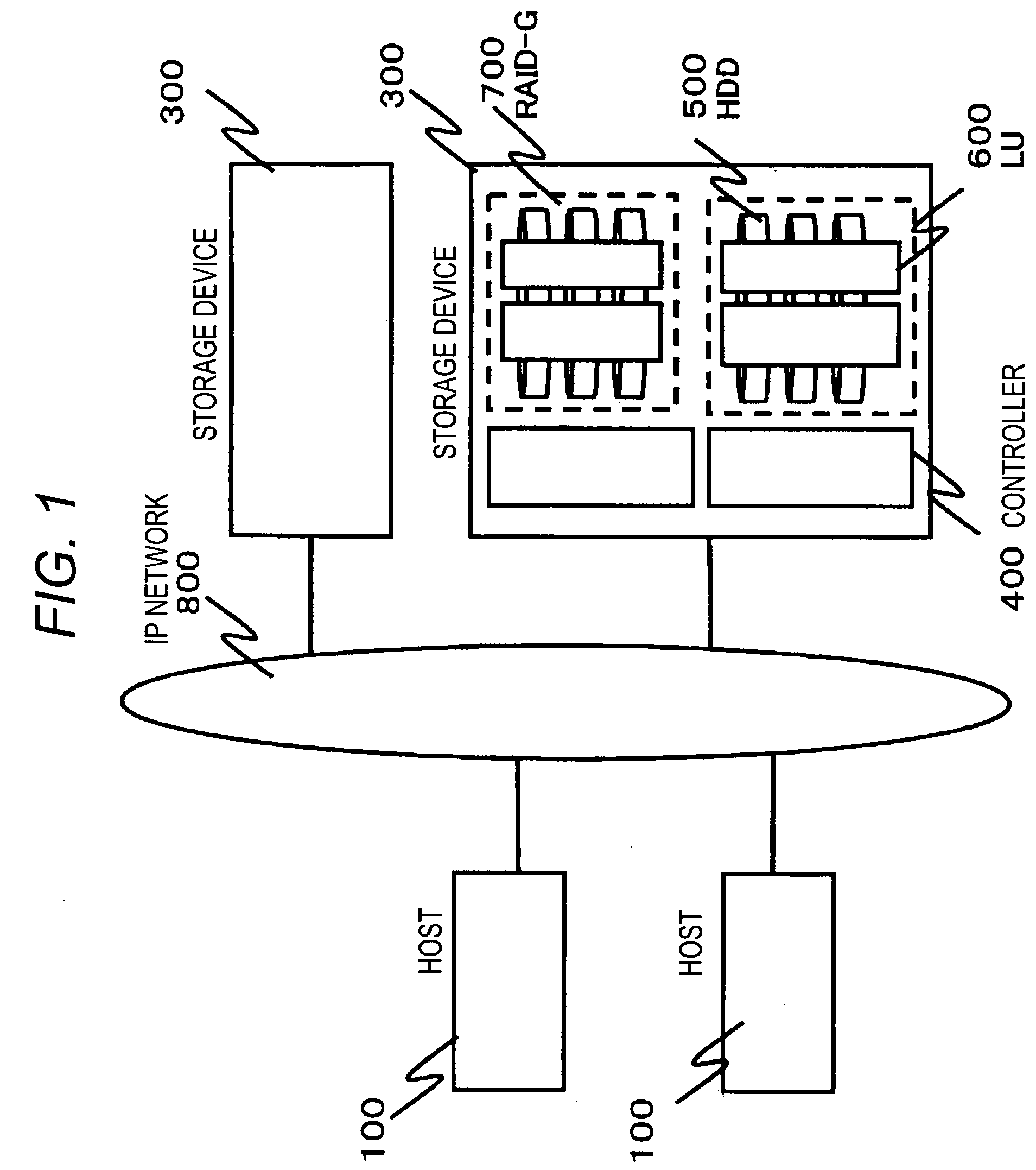
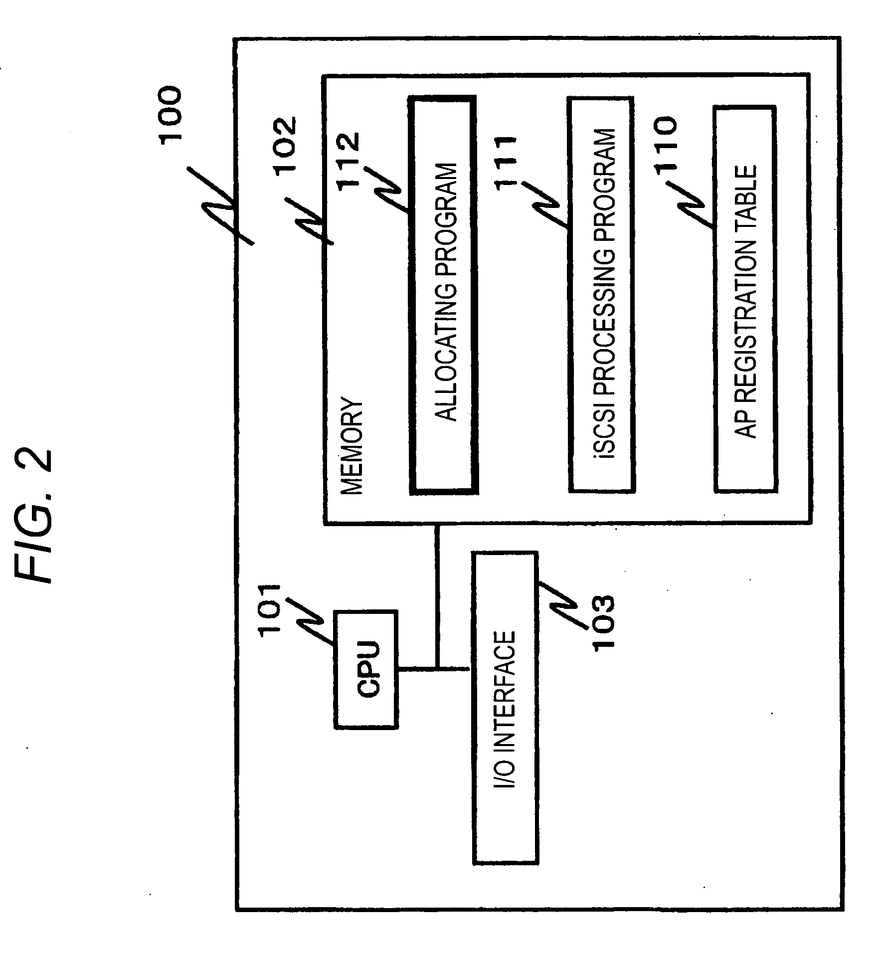
[0027]First, the configuration of a system according to the invention will be described. The schematic configuration of a computer system according to an embodiment of the invention will be described with reference to FIGS. 1, 2 and 5. FIG. 1 is an explanatory diagram showing the schematic configuration of the computer system according to the embodiment. FIG. 2 is an explanatory diagram conceptually showing the internal configuration of each host in the embodiment. FIG. 5 is an explanatory diagram conceptually showing the internal configuration of a controller of each storage device in the embodiment.

[0028]As shown in FIG. 1, the computer system according to the embodiment includes hosts 100, and storage devices 300. The hosts 100 are used by users. The storage devices 300 have logical units (LUs) 600 used by the hosts. The hosts 100 and the storage devices 300 are connected to one another through an IP (Internet Protocol) network 800. The IP network 800 is a local area network (LAN...

embodiment 2

[0056]A process for allocating a new volume to an application will be described with reference to FIGS. 11, 12, 13, 15 and 17.

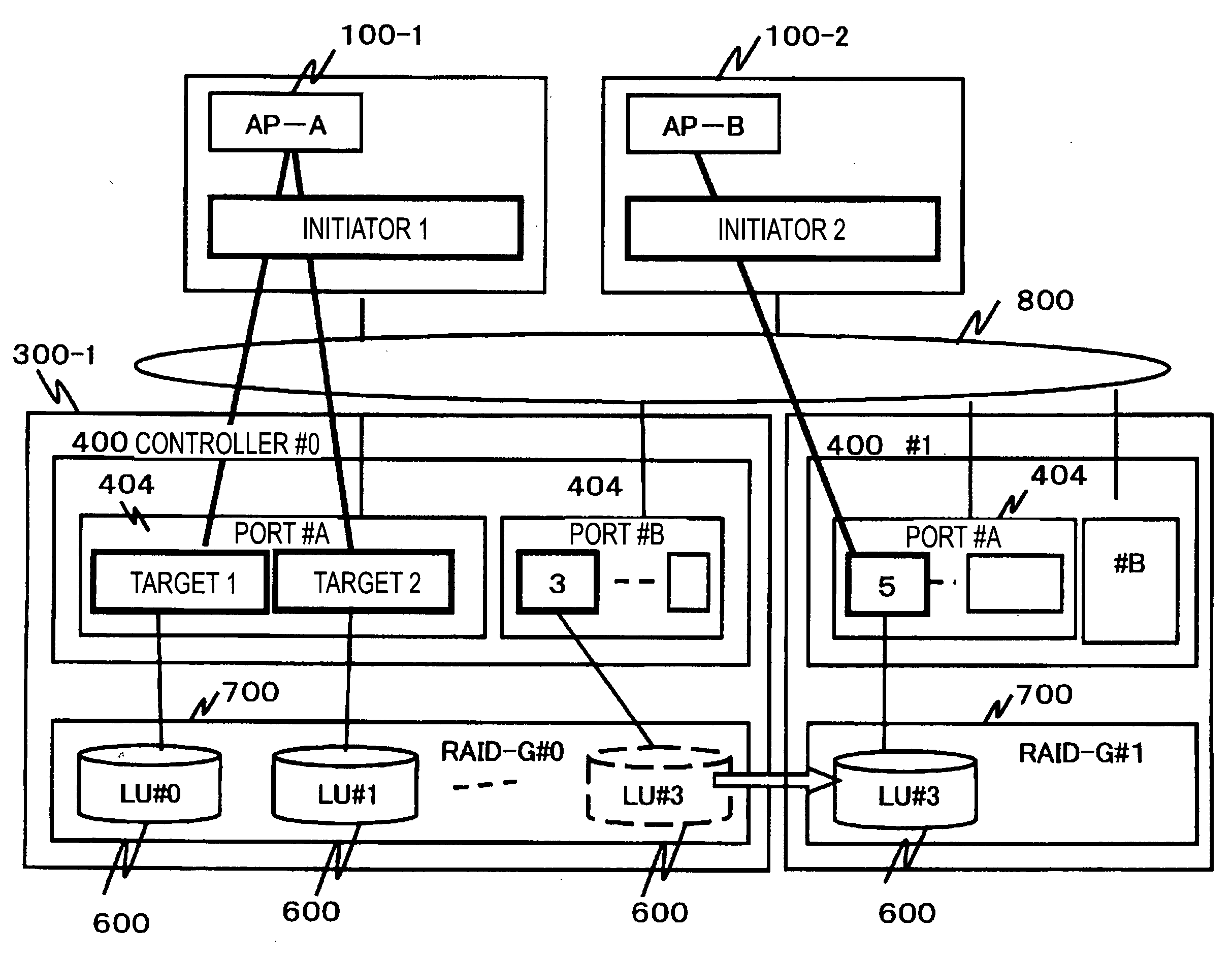
[0057]FIG. 11 is a diagram showing the LU configuration after new registration of an application. The reference numeral 110-2 designates the AP registration table of the host 100-2. As shown in FIG. 12, the reference numeral 110-2A designates the AP registration table before AP registration, and the reference numeral 110-2B designates the AP registration table after AP registration. As shown in FIG. 14, the reference numerals 410-1B, 410-2B, 410-3B and 410-4B designate the AP table, the volume table, the AP-volume correspondence table and the volume-RAID-G correspondence table, respectively, after AP registration.

[0058]FIG. 15 is a flow chart showing an allocation process in Embodiment 2 of the invention. FIG. 17 is a sequence diagram showing the allocation process in Embodiment 2 of the invention.

[0059]An administrator registers an APID (AP-C) and a volume I...


PUM


Abstract

The work load imposed on an administrator increases because the administrator has heretofore performed the work of allocating volumes to applications of PC server devices and the work of taking over volumes for applications in accordance with change in PC server devices. To solve this problem, there is provided a volume management system in a computer system having storage devices each of which has a unit which manages volume configuration information in accordance with each application, a unit which manages volume usage information in accordance with each of volumes for the applications, and a unit which manages allocatable areas of the storage devices while partitioning the allocatable areas of the storage devices in accordance with performance and reliability, wherein the volume management system has: a unit which selects suitable allocation regions in accordance with the volume usages of the applications; a unit which selects a suitable allocation region in accordance with change of host performance and migrates a volume to the suitable allocation region when host configuration of an application is changed; and a unit which changes configuration information to perform change of setting on each host.

Description

CROSS REFERENCES TO RELATED APPLICATIONS[0001]This application relates to and claims priority from Japanese Patent Application No. 2008-256314, filed on Oct. 16, 2008, the entire disclosure of which is incorporated herein by reference.1. FIELD OF THE INVENTION[0002]The present invention relates to a volume management system in a computer system in which disks equivalent to local disks of host computers are integrated into network-type storage devices so that the host computers can use these disks via a storage area network (SAN).2. DESCRIPTION OF THE RELATED ART[0003]Network-type storage devices (hereinafter referred to as storage devices) which can be connected to host computers by iSCSI (internet Small Computer System Interface) or FC (Fibre Channel) have come into practical use in recent years. In a computer system using such storage devices, the storage devices are logically partitioned into storage areas called LUs (Logical Units) so that each host can use the LUs in place of l...

Claims


Application Information

Patent Timeline
IPC IPC(8): G06F12/00G06F12/02G06F12/16
CPCG06F3/0605G06F3/067G06F3/0647G06F3/0635
Inventor KOBAYASHI, IKUKO
Owner HITACHI LTD
Why Eureka
Try Eureka