
Recessed Cutting Edge For Wire Cutting Gate Valves

a gate valve and cutting edge technology, applied in the field of gate valves, can solve the problems of reducing sealing capacity, reducing the durability of inlay materials, and unable to remove wirelines prior to valve closur

Active Publication Date: 2010-04-29
VETCO GRAY
View PDF10 Cites 30 Cited by
  • Summary
  • Abstract
  • Description
  • Claims
  • Application Information

AI Technical Summary

Problems solved by technology

However, in some situations wireline removal prior to valve closure is not possible and the gate valve is closed on the wireline.
Inlay materials are generally not as durable as gate valve materials and can be easily scratched or damaged, thereby reducing sealing capacity.

Method used


Image

  • Recessed Cutting Edge For Wire Cutting Gate Valves
  • Recessed Cutting Edge For Wire Cutting Gate Valves
  • Recessed Cutting Edge For Wire Cutting Gate Valves

Examples


Embodiment Construction

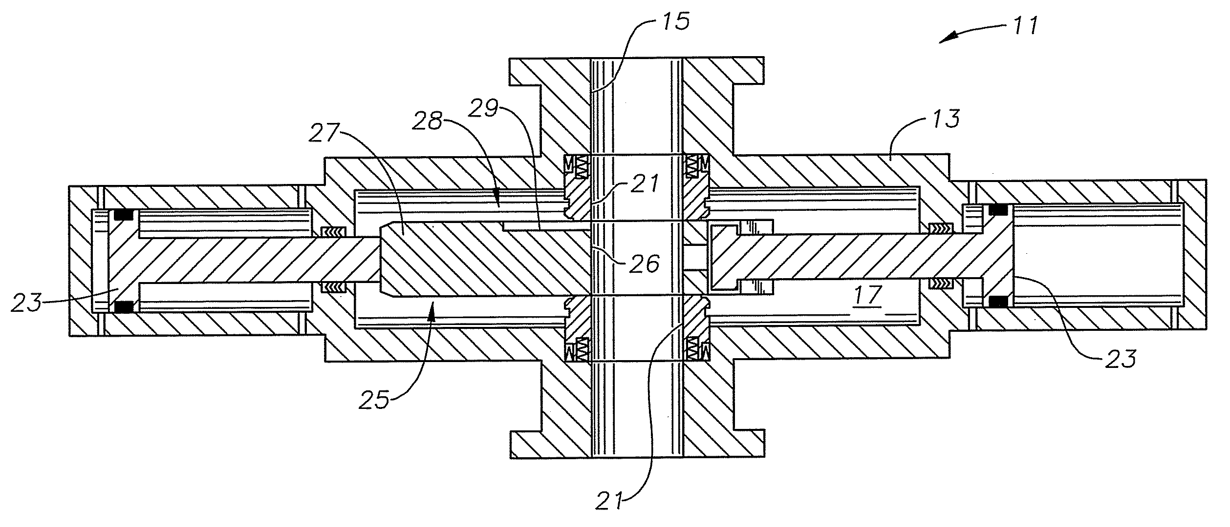
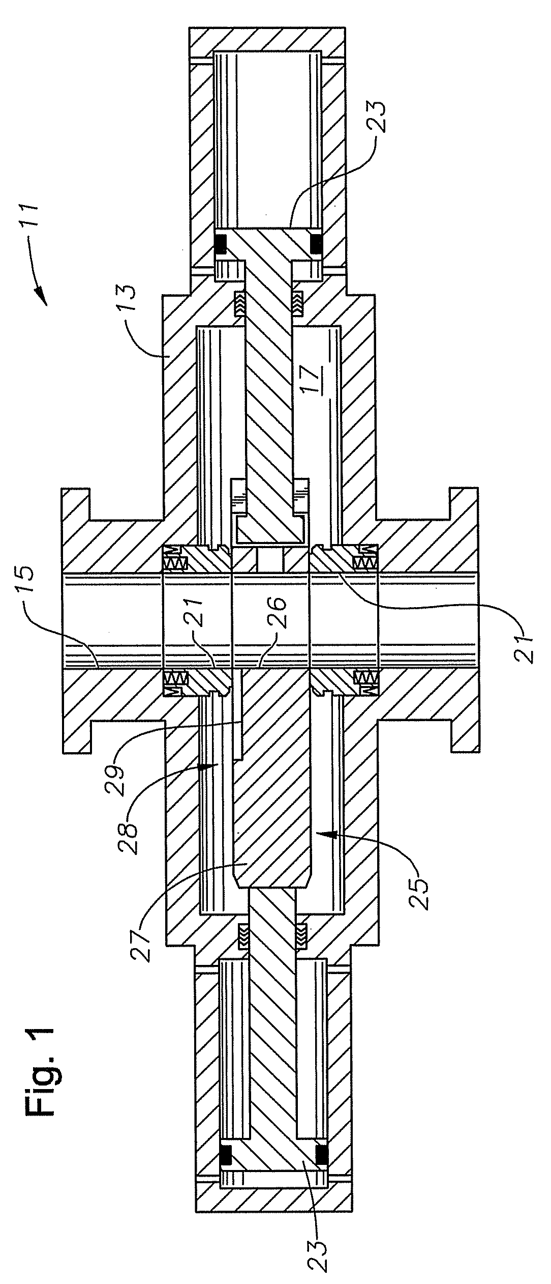
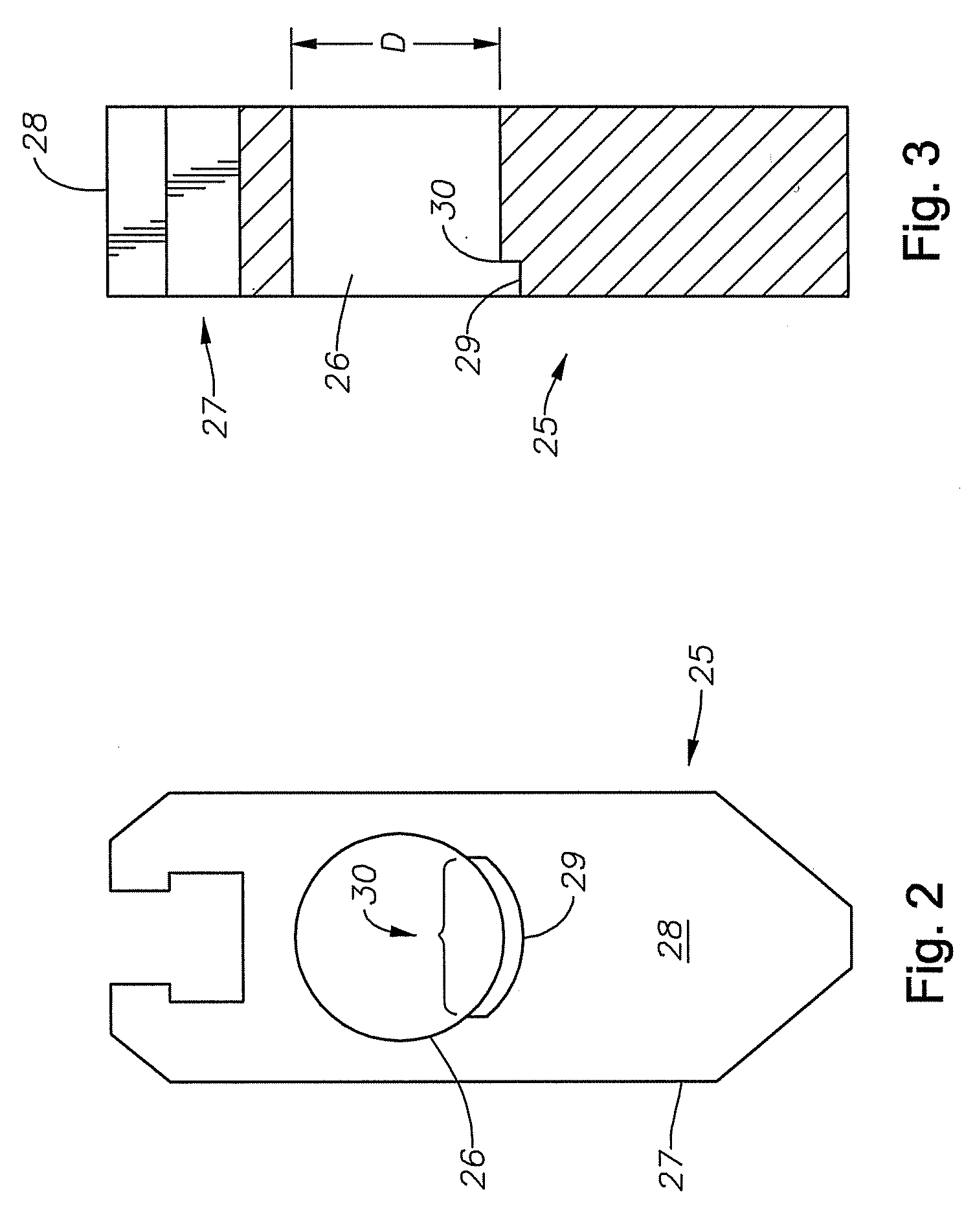
[0011]FIG. 1 provides a side sectional view of an embodiment of a gate valve 11. The gate valve comprises a body 13 housing a chamber 17 therein and a passage 15 formed through the body 13 that intersects the chamber 17. A gate 25 is shown within the chamber 17 that is a generally planar member having a solid portion 27 and an opening 26 formed through the solid portion 27. The gate 25 is selectively slidable within the chamber 17. Annular valve seats 21 are shown co-axially disposed in the passage 15, each having an end extending into the chamber 17. In the embodiment of the valve assembly 11 shown in FIG. 1, the opening 26 is registered with the passage 15, thereby placing the valve assembly 11 in the open position, allowing flow through the passage 15.

[0012]While in the open position the valve seats 21 sealingly contact the solid portion along an annular surface that circumscribes the opening 26. The sealing contact provides a pressure seal between the chamber 17 and passage 15. ...


PUM


Abstract

A gate valve having a body, a chamber housed in the body, a passage through the body that intersects the chamber, a gate for selectively opening and closing the valve, and a cutting edge on the gate. The cutting edge can sever any lines that may be in the valve and still seal after closing. The gate includes a recess formed to collect cuttings formed while severing the line.

Description

FIELD OF THE INVENTION[0001]This invention relates in general to gate valves, and in particular to an improved gate and valve face contoured to shear a line and maintain a seal across the valve after shearing.BACKGROUND OF THE INVENTION[0002]During oil and gas production, wirelines are often lowered through some type of gate valve. Ideally, the wireline is removed from the well before the gate valve is closed. However, in some situations wireline removal prior to valve closure is not possible and the gate valve is closed on the wireline. Gate valves having wireline therethrough should be capable of shearing the wireline while closing and maintain a seal after the valve is seated. Accordingly, the gate valve sealing surfaces should be durable and able to withstand repeated cycling; this is especially true for gate valves used in the oil and gas industry. Since the valves are opened and closed often and usually under severe operating conditions, the durability of the sealing surfaces ...

Claims


Application Information

Patent Timeline
Patent Type & Authority Applications(United States)
IPC IPC(8): F16K3/30
CPCE21B29/04F16K3/02E21B33/061F16K3/0281
Inventor LIEW, JOSEPH S. Y.
Owner VETCO GRAY
Features
  • Generate Ideas
  • Intellectual Property
  • Life Sciences
  • Materials
  • Tech Scout
  • Unparalleled Data Quality
  • Higher Quality Content
  • 60% Fewer Hallucinations
Learn More