Automatic timing adjustment system for occupancy sensors

a technology of occupancy sensor and automatic adjustment, which is applied in the direction of electric variable regulation, process and machine control, instruments, etc., can solve the problems of wasting energy, unable to determine the ideal duration of the timer, and occupants' light being turned o

Active Publication Date: 2010-04-29
SCHNEIDER ELECTRIC USA INC
View PDF7 Cites 19 Cited by
  • Summary
  • Abstract
  • Description
  • Claims
  • Application Information

AI Technical Summary

Problems solved by technology

Determining the ideal duration of the timer can be a difficult chore.
If the timer duration is too short, then it is likely that the light will turn OFF on the occupant.
If the timer duration is too long, then the lights will remain ON longer than necessary after the occupant leaves the room, wasting energy.
A false OFF can be a safety problem as well as an annoyance, so a longer than necessary time duration usually takes precedence over the need for energy savings.
There are problems with these existing methods.
A statistical approach requires a great deal of data before it can zero in on the best setting, making it s inherently slow to adjust in new occupancies or when the type of occupancy changes.
However, the drawback to this approach is that the timer duration will never be reduced when the type of occupancy changes.
It is also more likely that all reactive sensors will eventually arrive at the maximum timer setting, wasting energy.
Currently available reactive sensors typically make large adjustments in the timer (e.g., 1.5 times the existing value) so that the sensor reaches the maximum time-out very quickly to reduce annoyance to the occupants, but at is the expense of energy savings.
Manufacturers also are concerned with false ON events since such occurrences waste energy.
This method is not ideal since it introduces a time lag.
This may require further travel into a dark room, compromising safety.

Method used


Image

  • Automatic timing adjustment system for occupancy sensors
  • Automatic timing adjustment system for occupancy sensors
  • Automatic timing adjustment system for occupancy sensors

Examples


Embodiment Construction

[0015]Although the invention will be described in connection with certain preferred embodiments, it will be understood that the invention is not limited to those particular embodiments. On the contrary, the invention is intended to cover all alternatives, modifications, and equivalent arrangements as may be included within the spirit and scope of the invention as defined by the appended claims.

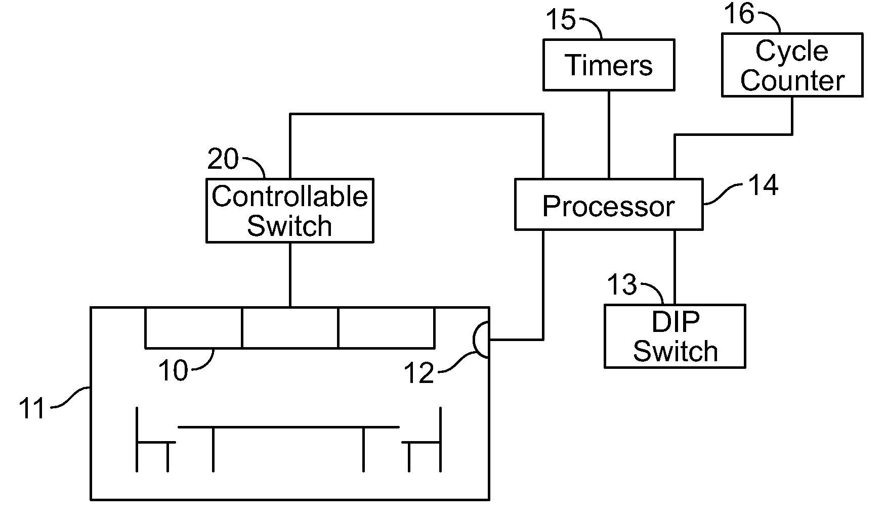
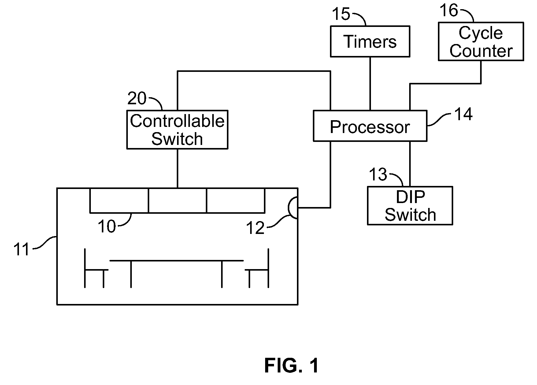
[0016]Turning now to the drawings, FIG. 1 is a diagram of a lighting control system for controlling the status of lamps 10 that artificially illuminate a space 11, such as a conference room, that contains an occupancy sensor 12. The control system includes a DIP switch 13 to permit the manual setting of a time-out period, and a processor (microcontroller) 14 connected to both the occupancy sensor 12 and the DIP switch 13. The processor 14 uses input signals, along with information that it stores regarding the operating history of the control system, to produce output signals that control the s...


PUM


Abstract

A lighting control system for a space equipped with lamps for illuminating the space comprises a power circuit for supplying power to the lamps, a controllable switch in the power circuit for turning the lamps on and off, an occupancy sensor for detecting motion within the space and generating a motion-detected control signal in response to the detection of such motion, and a timer for measuring a time-out interval following the generation of the motion-detected control signal by the occupancy sensor and producing a time-out control signal in response to completion of the measurement of the time-out interval. A processor receives the control signals from the occupancy sensor and the timer and produces a switch-off control signal for the controllable switch to turn the lamps off in response to the time-out control signal, modifies the time-out interval by a time-out offset value in response to preselected events, counts the number of times the switch-off control signal is produced, without the receipt of the motion-detected control signal, within a predetermined time following the end of the time-out interval, and decrements the time-out interval by the offset value in response to the count reaching a predetermined value.

Description

FIELD OF THE INVENTION[0001]The present invention relates to the use of occupancy sensors for controlling and, more particularly, to an improved automatic timing adjustment system for occupancy sensors.BACKGROUND OF THE INVENTION[0002]Automatic shut-off lighting controls are used to save electrical energy, and are often required by legislated energy codes. Occupancy sensors are intended to keep lights ON while people are within the detection area. Detection is based on movement, which is typically sensed using passive infrared (PIR) or ultrasonic doppler shift means. When the occupant is stationary or does not move to a great enough degree is to trigger detection, then the lights will turn OFF. To avoid this undesired consequence, a timer is employed to delay the OFF event. Ideally, this timer is set to a time that is at least the time between occupant movements such that the occupant will move again before the lights turn OFF. Determining the ideal duration of the timer can be a di...

Claims


Application Information

Patent Timeline
Patent Type & Authority Applications(United States)
IPC IPC(8): H05B37/02
CPCY02B20/44H05B37/0227H05B47/115Y02B20/40
Inventor REID, DREW A.STOTTLEMYER, WILLIAMMURLEY, JR., JAMESRENEAU, CHARLESMOORE, ROBERT
Owner SCHNEIDER ELECTRIC USA INC
Why Eureka
Try Eureka