Method for the spatially resolved measurement of birefringence, and a measuring apparatus

a spatial resolution and measurement method technology, applied in the direction of optical radiation measurement, instruments, material analysis, etc., can solve the problems of insufficient spatial resolution measurement of axial stress birefringence (sbr) of blanks, insufficient in every case, and inability to produce sharply delimited and homogeneous illumination of image fields. , to achieve the effect of preventing spilt over

Inactive Publication Date: 2010-04-29
CARL ZEISS SMT GMBH
View PDF11 Cites 26 Cited by
  • Summary
  • Abstract
  • Description
  • Claims
  • Application Information

AI Technical Summary

Benefits of technology

[0019]In a particularly advantageous variant, the measuring light beam is produced by a measuring light source and is detected by a detector and during the relative movement the measuring light source is moved in common with the detector. The measuring light source and the detector together form a polarimeter, it being possible to provide the detector with an evaluation device in order to process the measured measurement data. As the light source

Problems solved by technology

When such optical elements are used in optical installations operated with polarized radiation, for example in illumination systems operated in a polarized fashion, it is possible for there to occur stress-induced polarization losses which in the case of an illumination system, for example, may make it difficult to produce a sharply delimited and homogeneously illuminated image field.
Investigations have shown that the spatially resolved measurement of the axial stress bire

Method used


Image

  • Method for the spatially resolved measurement of birefringence, and a measuring apparatus
  • Method for the spatially resolved measurement of birefringence, and a measuring apparatus
  • Method for the spatially resolved measurement of birefringence, and a measuring apparatus

Examples


Embodiment Construction

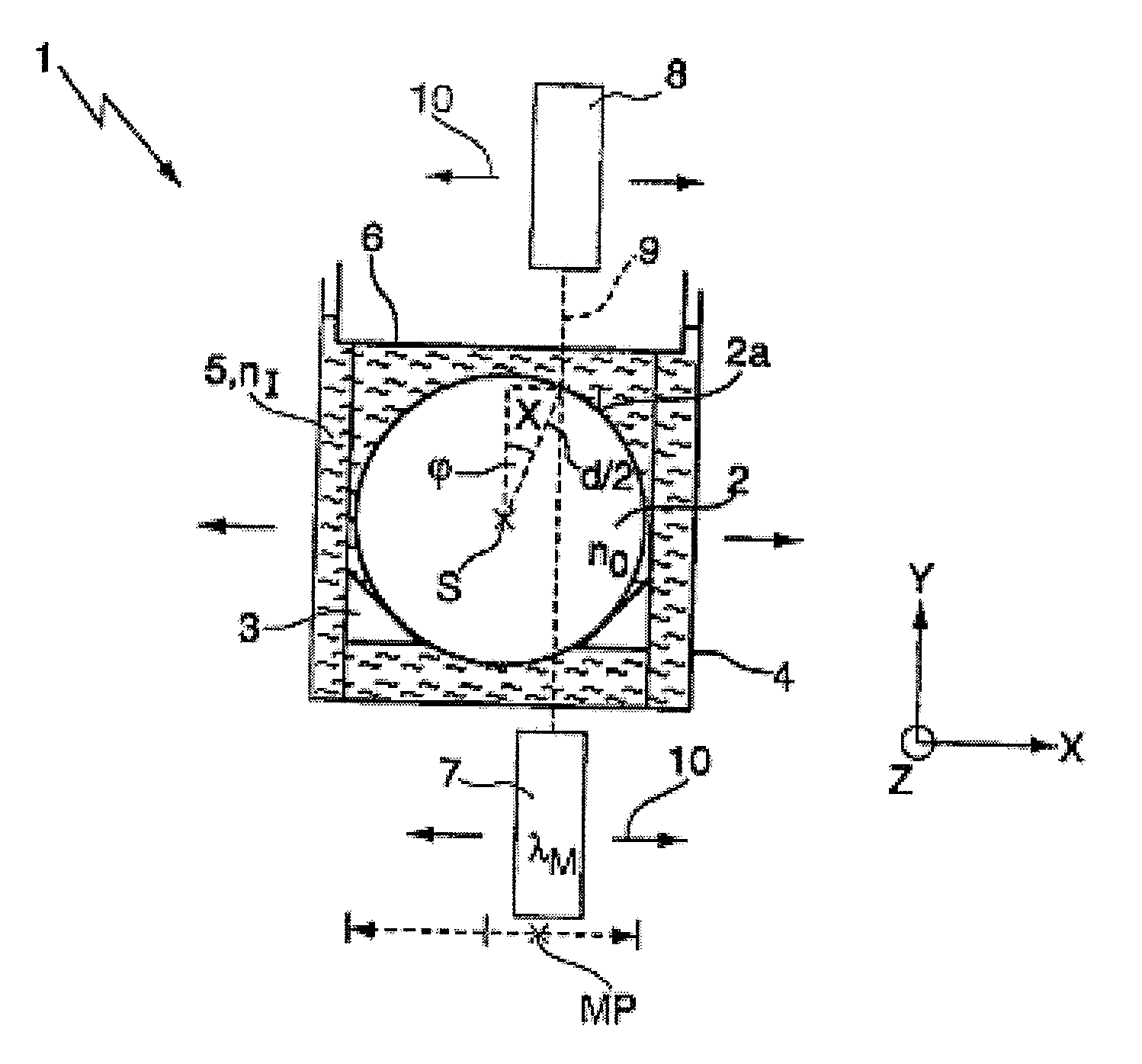
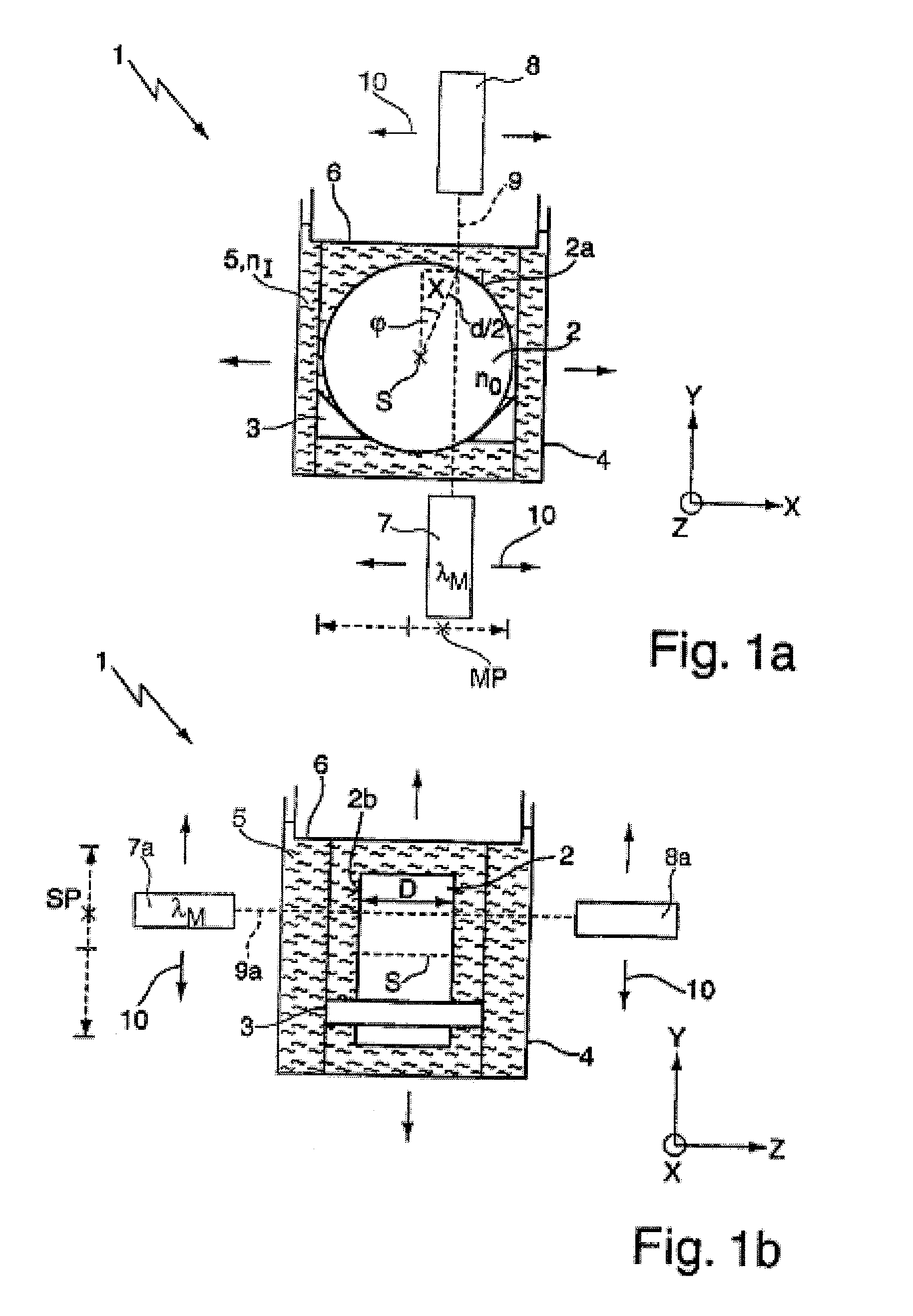
[0033]FIGS. 1a,b show diagrammatically a measuring apparatus 1 for the spatially resolved measurement of the birefringence distribution of a cylindrically symmetrical blank 2 made from synthetic calcium fluoride which is transparent to radiation at the operating wavelength λB of an optical element to be fabricated from the blank 2. It goes without saying that it is also possible to measure blanks made from other material, for example from silica glass, with the aid of the measuring apparatus 1. The blank 2 is arranged in a holder 3 in a container 4 formed as a cuboid cuvette. The container 4 is filled with an immersion fluid 5 which completely surrounds the blank 2. Both a cover 6, which delimits the immersion fluid 5 above, and the wall of the container 4 consist of a material transparent to VUV and visible radiation, for example of silica glass.

[0034]The measuring apparatus 1 further has a polarimeter 7, 8 which consists of a measuring light source 7 and a detector 8 which are arr...


PUM


Abstract

A method for the spatially resolved measurement of the birefringence distribution of a cylindrically symmetrical blank (2) made from an optical material transparent to at least one wavelength λB between 180 nm and 650 nm, in particular at 193 nm, including: irradiating the blank (2), arranged in a container (4) with an immersion fluid (5), at a jacket-side measurement position (MP) using a measuring light beam (9) which runs in a measuring direction (Y) preferably perpendicular to the axis of symmetry (S) of the blank (2), as well as varying the jacket-side measurement position (MP) by moving the measuring light beam (9) and the blank (2) relative to one another in two directions (X, Z) perpendicular to the measuring direction (Y) for the purpose of spatially resolved measurement of the non-axial birefringence distribution of the blank (2).

Description

[0001]The following disclosure is based on German Patent Application No. DE 10 2008 043 158.3, filed on Oct. 24, 2008, which is incorporated into this application by reference.BACKGROUND OF THE INVENTION[0002]The invention relates to a method for the spatially resolved measurement of the birefringence distribution of a cylindrically symmetrical blank made from an optical material transparent to at least one wavelength λB between 180 nm and 650 nm, in particular at 193 nm, as well as to a measuring apparatus for carrying out the method.[0003]Projection exposure machines for microlithography are usually operated at wavelengths below 250 nm, for example with pulsed lasers at an operating wavelength of, for example, 248 nm (KrF laser) or 193 nm (ArF laser). The birefringence of the optical material plays an important role in the case of the optical elements used in such machines, in particular in the case of lens elements. Birefringence designates the splitting of the incident radiation...

Claims


Application Information

Patent Timeline
IPC IPC(8): G01J4/00
CPCG01M11/0228G01N2021/178G01N21/23
Inventor PAHL, ULRICHSPANUTH, JENS
Owner CARL ZEISS SMT GMBH
Why Eureka
Try Eureka