

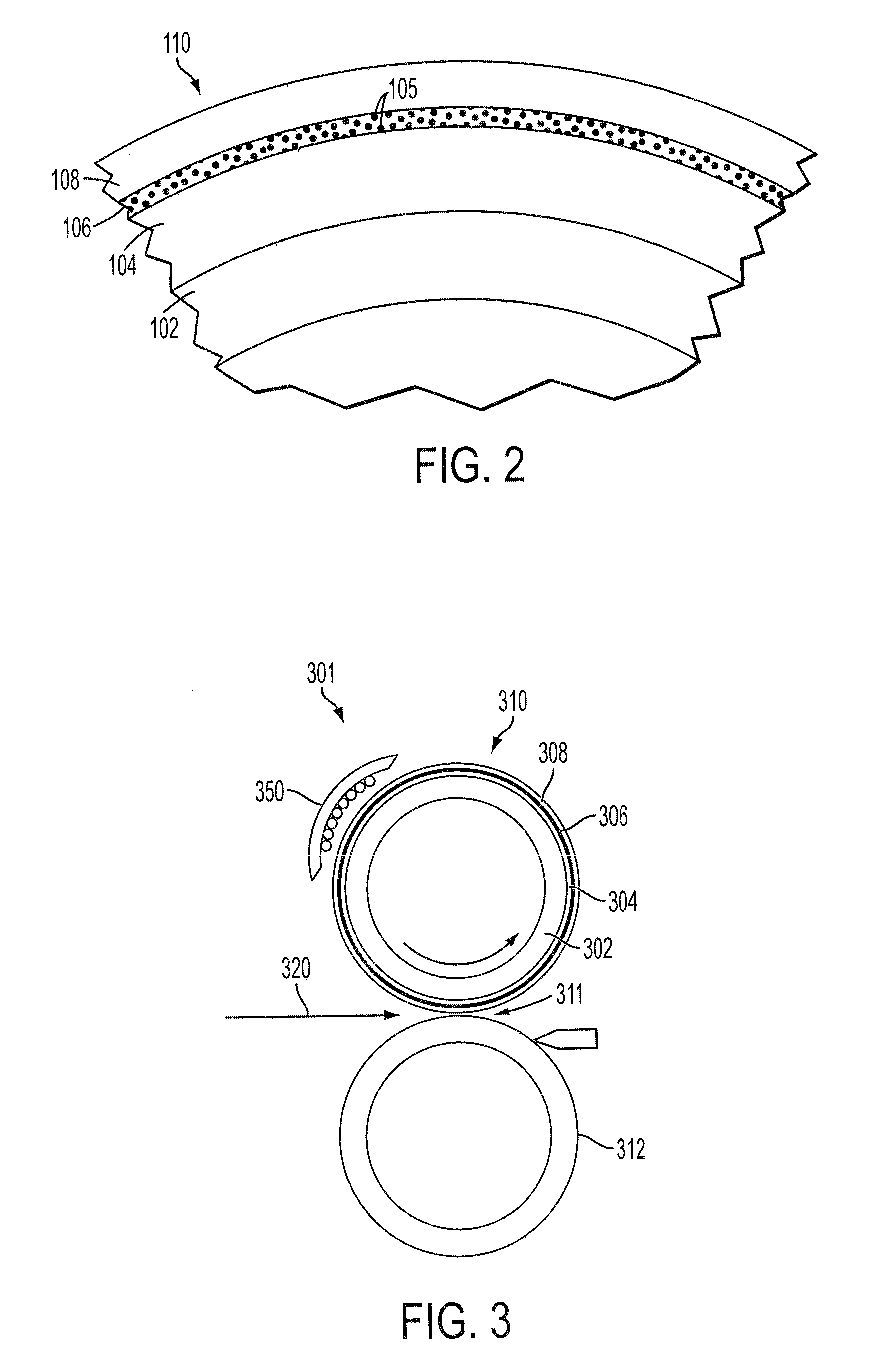
Nanomaterial heating element for fusing applications
a heating element and nanomaterial technology, applied in nanotechnology, electrographic process apparatus, instruments, etc., can solve the problems of inefficient energy consumption of current fusing system in marking (dry and direct) and long warm up tim
- Summary
- Abstract
- Description
- Claims
- Application Information
AI Technical Summary
Benefits of technology
Problems solved by technology
Method used
Image

Examples
Embodiment Construction
[0001]1. Field of the Invention
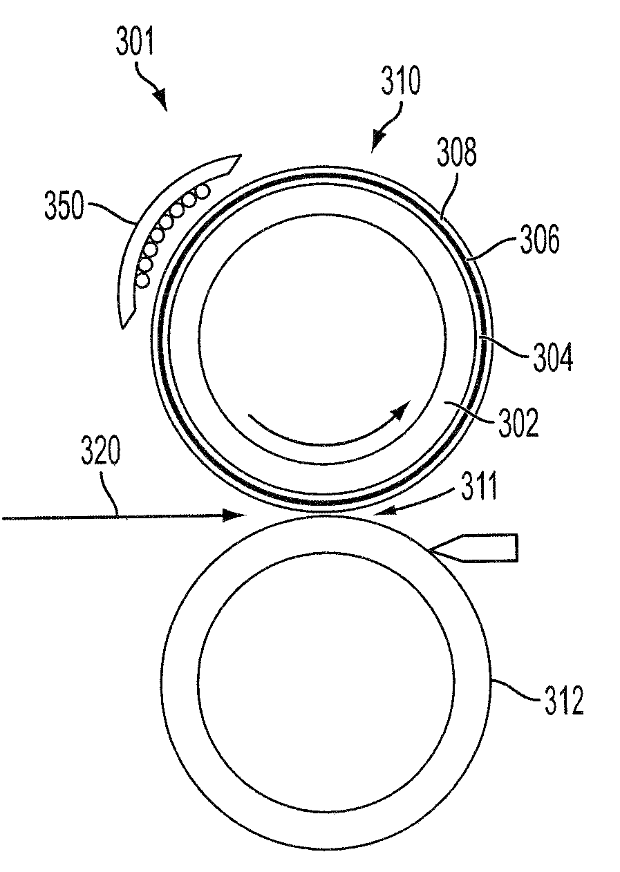
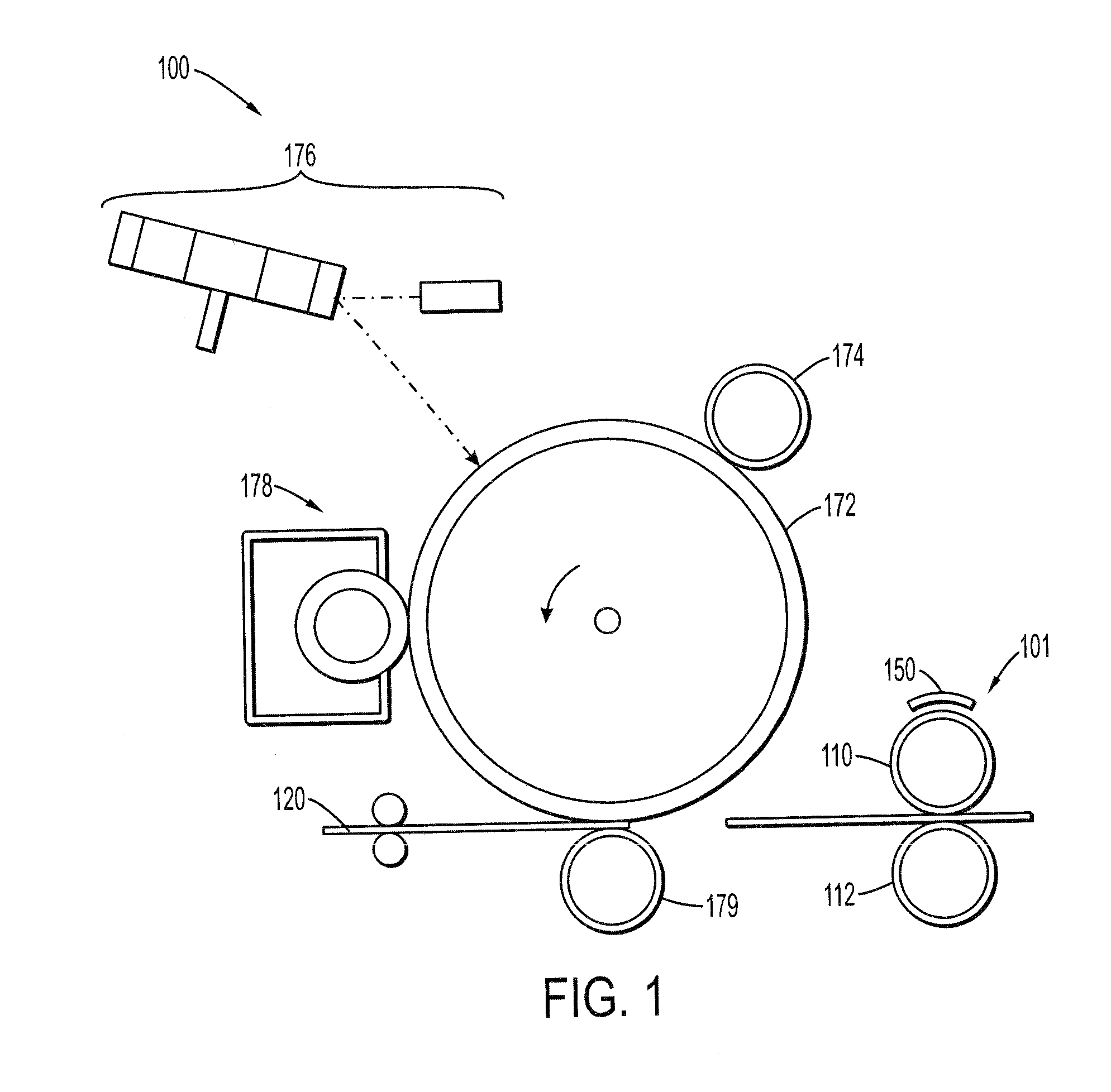
[0002]The present invention relates to printing and marking devices and more particularly to fuser subsystems and methods of using them.
[0003]2. Background of the Invention
[0004]Current fusing systems in marking (dry and direct) are very inefficient in regards to energy consumption. For example, in a typical fuser roll, only about 1% of the heat is used to fix the toner images, the rest is split between warming up the paper and simply waste due to heating up the roll and during standby. Also, as a result of the large heating mass, the warm up time can be very long, for example, up to about 30 minutes for large production machines.
[0005]Accordingly, there is a need to overcome these and other problems of prior art to provide fusing subsystems that can address all three concerns in, warm up time, energy efficiency, and heat addressability.
SUMMARY OF THE INVENTION
[0006]In accordance with various embodiments, there is a printing apparatus. The printing app...
PUM
| Property | Measurement | Unit |
|---|---|---|
| length | aaaaa | aaaaa |
| length | aaaaa | aaaaa |
| thickness | aaaaa | aaaaa |
Abstract
Description
Claims
Application Information