Independent brake control of a common aircraft gear

a technology of aircraft gear and brake control, applied in aircraft braking arrangements, instruments, navigation instruments, etc., can solve problems such as dynamic instability and problems that can aris

Active Publication Date: 2010-04-29
THE BF GOODRICH CO
View PDF9 Cites 19 Cited by
  • Summary
  • Abstract
  • Description
  • Claims
  • Application Information

AI Technical Summary

Problems solved by technology

Problems can arise, however, with the use of multiple brake control channels.
Additionally, it is possible that two independent control channels could control the brakes in a way that causes dynamic instability—like twisting the gear when the brake applications get out of phase.

Method used


Image

  • Independent brake control of a common aircraft gear
  • Independent brake control of a common aircraft gear
  • Independent brake control of a common aircraft gear

Examples


Embodiment Construction

[0023]The present invention will now be described with reference to the drawings, wherein like reference numerals are used to refer to like elements throughout. Because the invention was conceived and developed for use in an aircraft braking system, it will be herein described chiefly in this context. However, the principles of the invention in their broader aspects can be adapted to other types of braking systems.

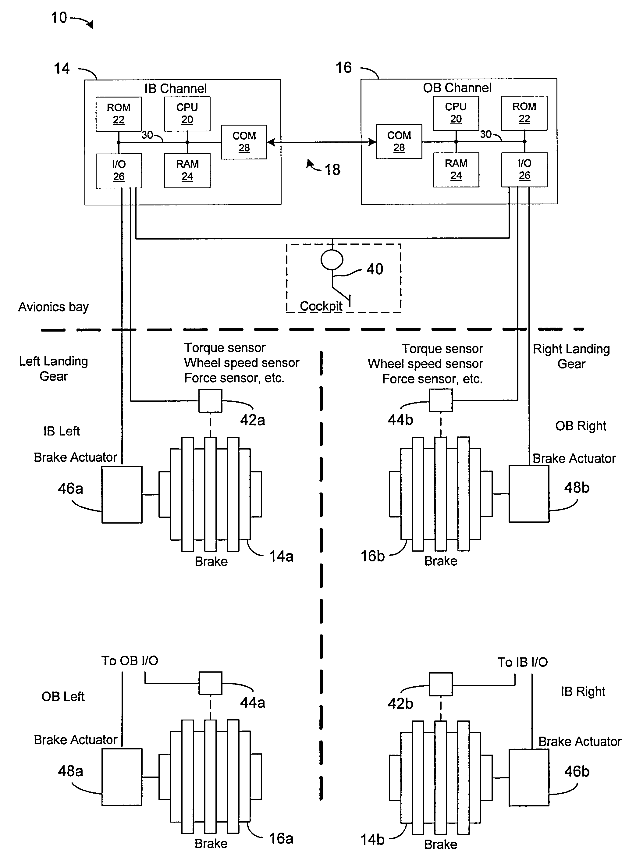
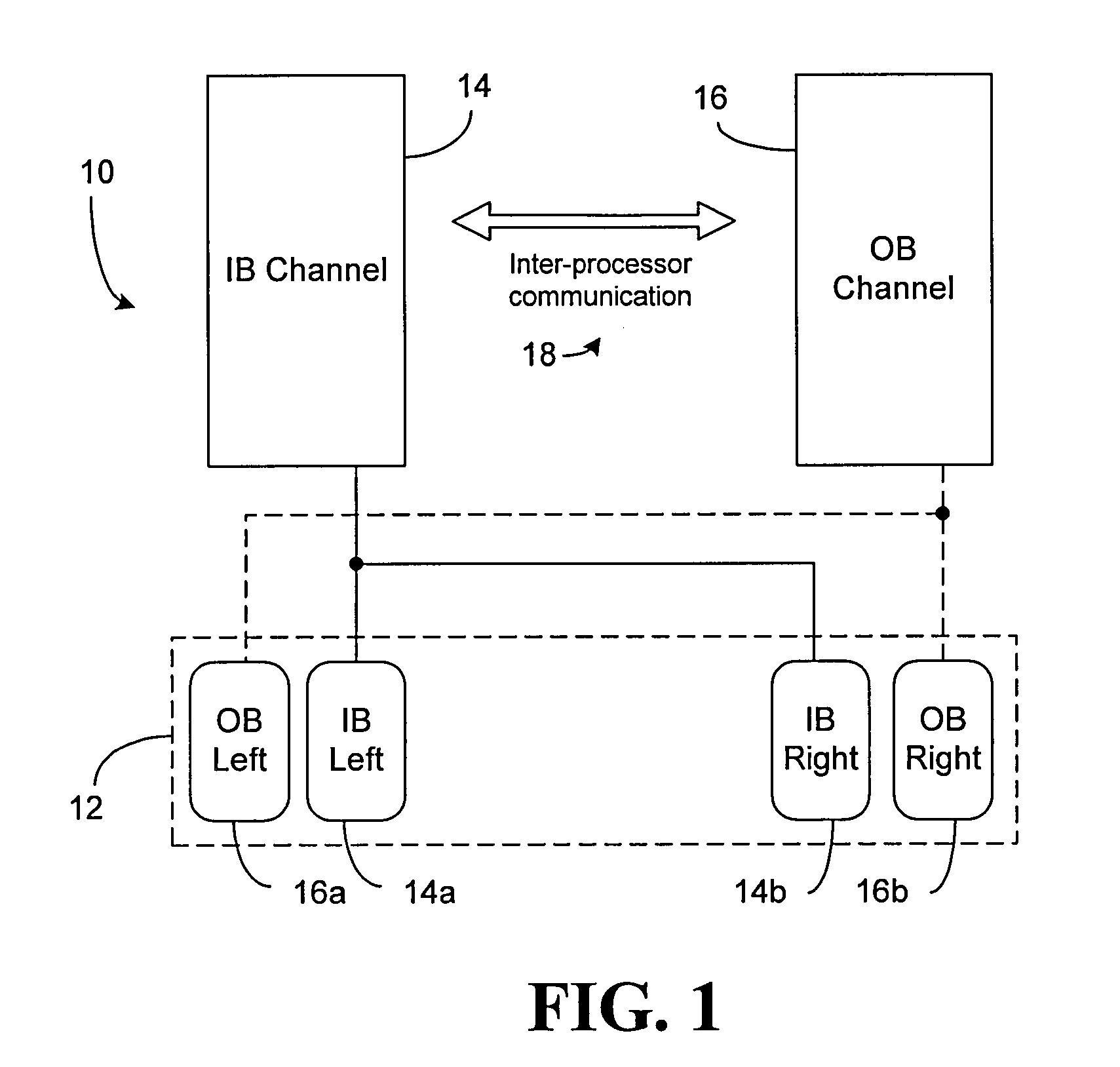
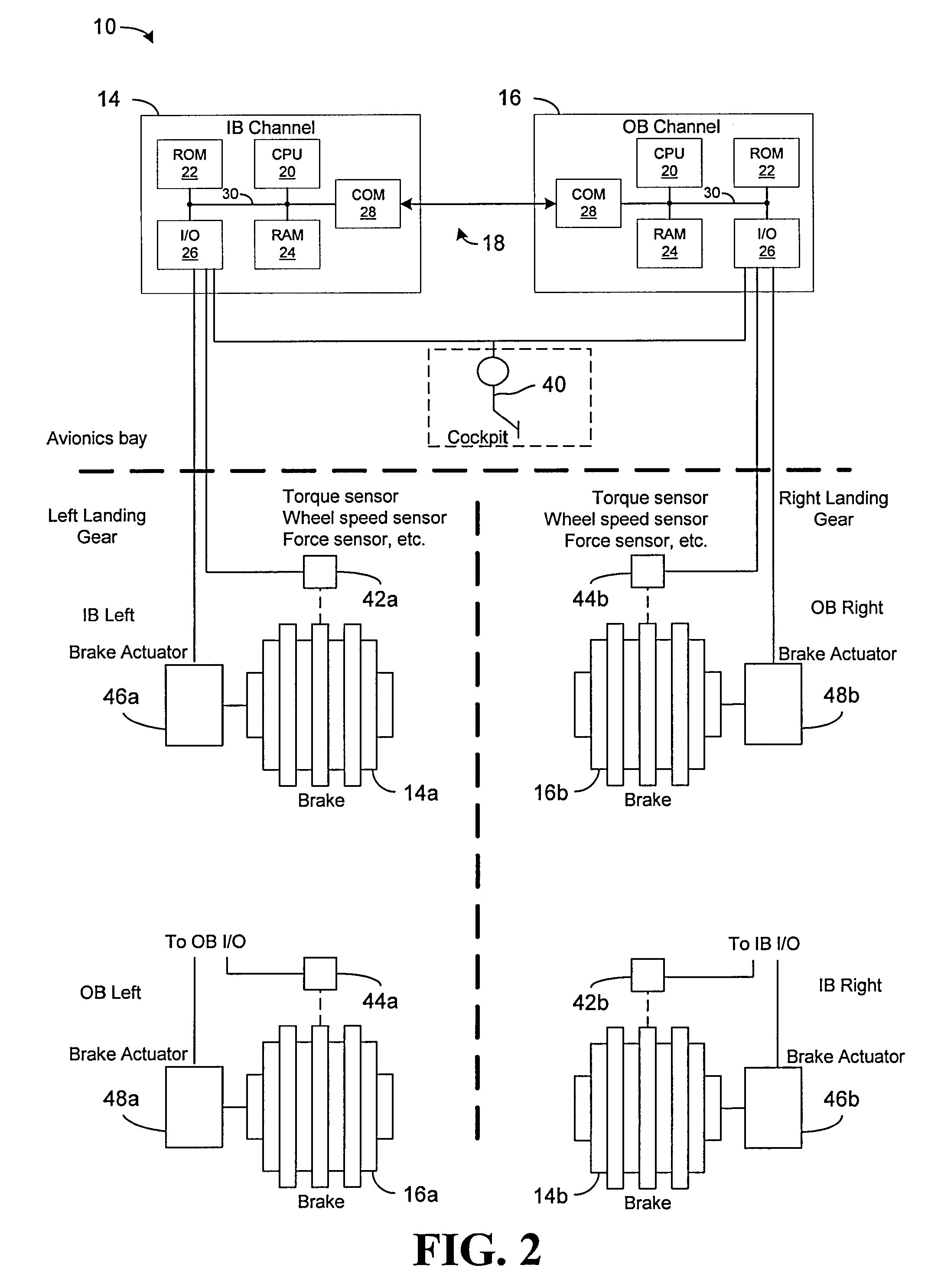
[0024]Referring to FIG. 1, the general architecture of a brake control system 10 is shown in accordance with an exemplary embodiment of the present invention. The brake control system 10 serves to control the brakes on a landing gear 12, for example. The landing gear 12 includes an inner bank (IB) left brake 14a and outer bank (OB) left brake 16a on a left side of the landing gear 12, and an IB right brake 14b and OB right brake 16b on the right side of the landing gear 12. The IB left Brake 14a and the OB left brake 16a may serve to apply braking to a same wheel or differ...


PUM


Abstract

A brake control system for a landing gear of an aircraft is provided. The system includes a first control channel for providing brake control signals to one or more brakes on the landing gear, and a second control channel for providing brake control signals to another one or more brakes on the landing gear. At least one of the first control channel and the second control channel is configured to act as an executive in monitoring braking efforts applied by the one or more brakes as compared to braking efforts applied by the another one or more brake, and to cause the braking efforts of at least one of the one or more brakes or the another one or more brakes to be modified in an effort to equalize the braking efforts.

Description

RELATED APPLICATION DATA[0001]This application claims priority of U.S. Provisional Application No. 60 / 939,056 filed on May 19, 2007, which is incorporated herein by reference in its entirety.TECHNICAL FIELD[0002]The present invention relates generally to brake control systems, and more particularly to a system, device and method for controlling multiple brakes on a given gear of an aircraft.BACKGROUND OF THE INVENTION[0003]Aircraft brake control systems are known in the art. These brake control systems function to provide brake control to brakes on the landing gear of the aircraft. The brakes exert a braking force on the wheels of the gear in order to slow the aircraft during taxiing, landing, rejected take-off, etc.[0004]For reasons such as system redundancy and / or robustness, a brake control system may include multiple brake control channels controlling respective brakes on a given gear. The multiple brake control channels may serve to control respective brakes (e.g., respective b...

Claims


Application Information

Patent Timeline
Patent Type & Authority Applications(United States)
IPC IPC(8): G06F19/00B60T8/17
CPCB60T8/1703B64C25/44
Inventor CAHILL, ERIC D.
Owner THE BF GOODRICH CO
Why Eureka
Try Eureka