
Aircraft cabin lighting system and kit therefor

Inactive Publication Date: 2010-05-06
BE AEROSPACE INCORPORATED
View PDF14 Cites 47 Cited by
  • Summary
  • Abstract
  • Description
  • Claims
  • Application Information

AI Technical Summary

Problems solved by technology

Certification is made difficult because refurbishing, upgrading or otherwise customizing the aircraft cabin interior has, until now, entailed the use of custom-designed products.

Method used


Image

  • Aircraft cabin lighting system and kit therefor
  • Aircraft cabin lighting system and kit therefor
  • Aircraft cabin lighting system and kit therefor

Examples


Embodiment Construction

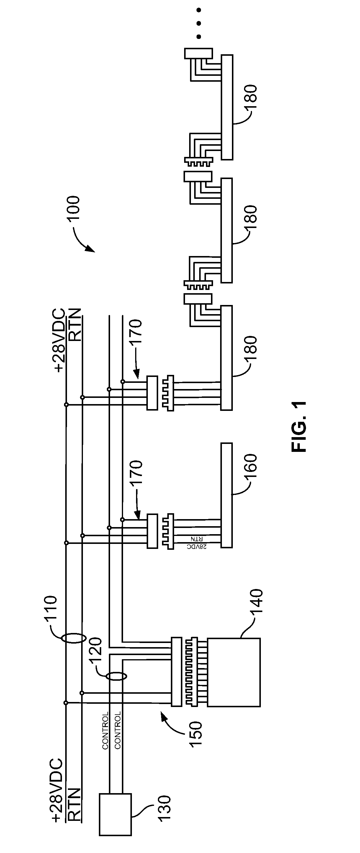
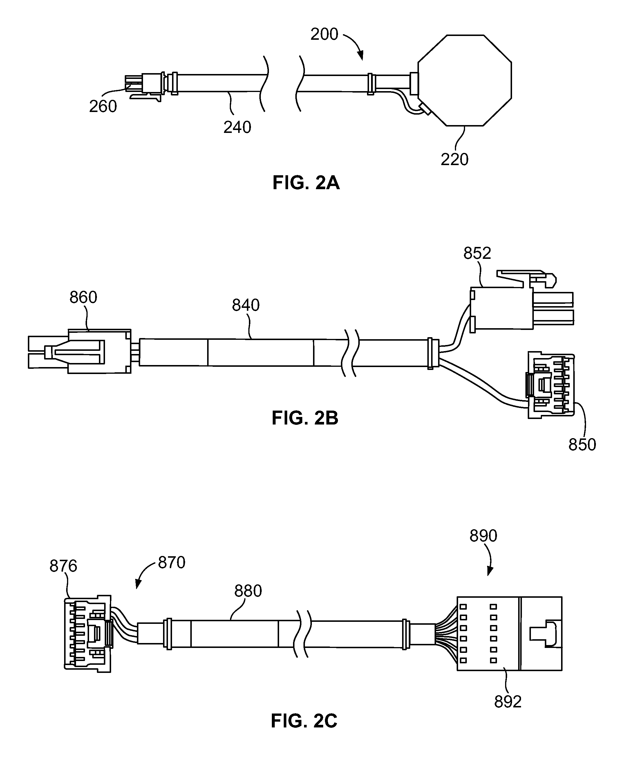
[0025]Turning now to the Figures, an aircraft cabin lighting system and kit are provided. FIG. 1 illustrates an example aircraft cabin lighting system. As shown in FIG. 1, the aircraft cabin lighting system 100 includes a power bus 110, a communication bus 120, a cabin management system 130, a dimmer / driver module 140, and a plurality of lighting units 160, 180. The cabin management system (CMS) 130 may be user interface such as a computer with a display and an input device (e.g., a keyboard and / or a mouse), a touch-screen, a flight attendant or crew panel with actuators (e.g., buttons, switches, etc.) and the like for operating / controlling lights, the crew intercom, and overhead announcement speakers as well as other cabin environmental and entertainment features. The CMS 130 is in communication with the aircraft communication bus 120 for outputting command signals to the communication bus 120 and for receiving signals (e.g., status signals and the like) via the communication bus 1...


PUM


Abstract

An aircraft cabin lighting kit includes: a driving / dimming module generating output signals for controlling illumination of at least one lighting unit according to command signals from a cabin management system; and at least one wire assembly interfacing the driving / dimming module with a power bus for receiving operational power, and a communication bus for receiving the command signals and for communicating the output signals to the at least one lighting unit. The present aircraft cabin lighting kit is certified by a governmental aviation-regulating body for installation in multiple aircraft. An aircraft cabin lighting system, which includes the kit, is also provided

Description

CROSS-REFERENCE TO RELATED PATENT APPLICATIONS[0001]This patent application is a continuation-in-part, of copending U.S. patent application Ser. No. 12 / 261,216, filed Oct. 30, 2008.FIELD OF THE INVENTION[0002]This invention pertains generally to aircraft interiors. More particularly, the present invention relates to an aircraft cabin lighting system and a kit for facilitating installation of the same.BACKGROUND OF THE INVENTION[0003]As known in the art, items (e.g., systems, sub-systems and components) that are installed on aircraft need to be reviewed and approved by a governmental aviation-regulating body to ensure that such items comply with applicable standards (e.g., airworthiness and other safety concerns). For example, in the United States the Federal Aviation Administration (FAA) requires any person or company producing replacement or modification parts for installation on a type-certificated product (i.e., aircraft) to obtain a parts manufacturer approval (PMA), which is a ...

Claims


Application Information

Patent Timeline
IPC IPC(8): B64D47/02
CPCB64D47/02B64D2221/00B64D2203/00H05B37/0254H05B33/0872H05B33/0845H05B45/20H05B47/18H05B45/10
Inventor ECKEL, DAVID P.SECILMIS, SECKIN
Owner BE AEROSPACE INCORPORATED
Learn More