Method for monitoring downlink control channel in user equipements

a control channel and user technology, applied in the field of long-term evolution system, can solve problems such as power consumption, and achieve the effect of restoring a drx operation to be reliabl

Inactive Publication Date: 2010-05-06
LG ELECTRONICS INC
View PDF4 Cites 132 Cited by
  • Summary
  • Abstract
  • Description
  • Claims
  • Application Information

AI Technical Summary

Benefits of technology

[0027]An object of the present invention is to provide a method for rendering a DRX operation to be reliable desp

Problems solved by technology

If the UE continuously monitors a downlink channel carrying the radio resource allocation information, particularly a Physical Downlink Control Channel (PDCCH), pow

Method used


Image

  • Method for monitoring downlink control channel in user equipements
  • Method for monitoring downlink control channel in user equipements
  • Method for monitoring downlink control channel in user equipements

Examples


first exemplary embodiment

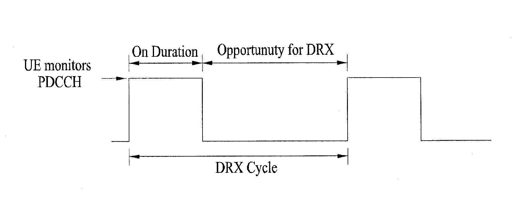
[0060]In accordance with a first exemplary embodiment of the present invention, the UE applies an operation modifying the DRX Start Offset received from the eNB when the Short DRX Cycle is used. This ensures that a subframe that satisfies the condition that the remainder of dividing [(SFN×10)+Subframe Number] by the Short DRX Cycle is equal to the modified DRX Start Offset will always exist.

[0061]An example of the operation modifying the DRX Start Offset can be a modulo operation. In particular, the modulo operation may be used to calculate the starting point of a Short DRX Cycle. Specifically, the UE performs a modulo operation with respect to the DRX Start Offset received from the eNB and uses the value after performing the modulo operation to determine the starting point of the On Duration Timer in the Short DRX Cycle. In this example, Table 2 is modified to Table 3 as shown below.

TABLE 3DRX Operation If the Short DRX Cycle is used and [(SFN × 10) + Subframe Number]modulo (Short ...

second exemplary embodiment

[0064]In the second exemplary embodiment of the present invention, when the eNB sets a plurality of DRX cycles for the UE, it notifies the UE of DRX Start Offsets for the respective DRX cycles. Upon receipt of DRX configuration information from the eNB, especially when the DRX configuration information indicates a plurality of DRX cycles, the UE uses the DRX Start Offsets set for the respective DRX cycles in calculating the starts of the DRX cycles. For example, when the eNB intends to set a Long DRX Cycle of 2560 ms and a Short DRX Cycle of 512 ms for the UE, it additionally notifies the UE of offset values for the two DRX cycles. For instance, the eNB can command the UE to use a DRX offset of 1000 for the Long DRX and a DRX offset of 488 for the Short DRX. Then the UE calculates DRX start time points using the DRX offsets received for the DRX levels, i.e., the Short and Long DRX Cycles. According to the second embodiment, Table 2 is modified to Table 4. Although signaling transmit...


PUM


Abstract

The method for discontinuously monitoring downlink control channel in a user equipment in a wireless communication system includes receiving a discontinuous reception (DRX) Start Offset from a base station to be used for both a first DRX Cycle and a second DRX Cycle, and starting an On Duration Timer at a subframe that satisfies either a first condition for the first DRX Cycle or a second condition for the second DRX Cycle, wherein a first DRX offset used in the first condition is based upon the DRX Start Offset received from the base station, and wherein a second DRX offset used in the second condition is based upon a remainder of the DRX Start Offset received from the base station after a modulo operation by the second DRX Cycle.

Description

[0001]This application also claims the benefit of U.S. Provisional Application Ser. No. 61 / 112,154, filed on Nov. 6, 2008 the content of which is hereby incorporated by reference herein.BACKGROUND OF THE INVENTION[0002]1. Field of the Invention[0003]The present invention relates to a Long Term Evolution (LTE) system, and more particularly to a method for monitoring a downlink control channel in a User Equipment (UE) in a wireless communication system.[0004]2. Discussion of the Related Art[0005]FIG. 1 illustrates a network structure of an Evolved Universal Mobile Telecommunication System (E-UMTS). An E-UMTS system is an evolved version of a Wideband Code Division Multiple Access (WCDMA) UMTS system, and its basic standardization is in progress under the 3rd Generation Partnership Project (3GPP). The E-UMTS is also referred to as an LTE system. Release 7 and Release 8 of “3rd Generation Partnership Project; Technical Specification Group Radio Access Network” are incorporated herein, a...

Claims


Application Information

Patent Timeline
IPC IPC(8): H04L12/26
CPCH04L43/0811H04W24/04
Inventor CHUN, SUNG DUCKYI, SEUNGJUNEPARK, SUNG JUN
Owner LG ELECTRONICS INC
Why Eureka
Try Eureka