Data center and data center design

a data center and data center technology, applied in the field of data center and data center design, can solve the problems of increasing redundancy equate, uninterruptible power supply (ups) and cooling equipment, and significantly increasing capital costs and operating costs

Inactive Publication Date: 2010-05-06
HEWLETT-PACKARD ENTERPRISE DEV LP
View PDF13 Cites 11 Cited by
  • Summary
  • Abstract
  • Description
  • Claims
  • Application Information

AI Technical Summary

Problems solved by technology

Such auxiliary equipment may include uninterruptible power supplies (UPS) and cooling equipment.
Unsurprisingly, increased redundancy equates to significantly increased capital costs and operating costs.

Method used


Image

  • Data center and data center design
  • Data center and data center design
  • Data center and data center design

Examples


Embodiment Construction

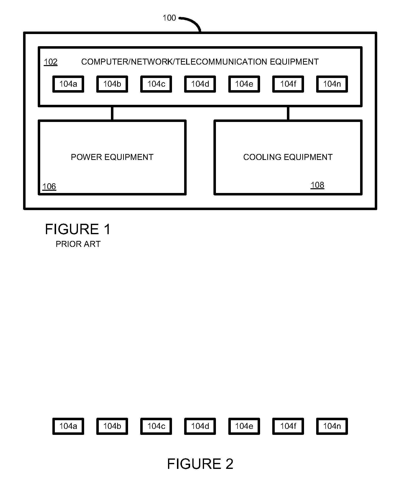
[0013]FIG. 1 shows a simplified block diagram of a monolithic tiered data center 100 according to the prior art. The data center 100 includes computing equipment 102, which may include computers, servers, networking, and telecommunication equipment, on which run numerous software applications 104a to 104n. The equipment 102 is powered by power equipment 106 and is cooled by cooling equipment 108. The exact nature of the power equipment 106 and cooling equipment 108 depends on the tier classification of the data center 100. For example, a tier 4 data center may have multiple power and cooling distribution paths including 2N+1 redundancy (i.e. 2 UPS each with N+1 redundancy), whereas a tier 1 data center may have only a single path for power and cooling distribution, with no redundant components.

[0014]Given the increasing operating costs of running a data center, especially with respect to power and cooling, data center operators are looking to reduce the cost of and improve the effic...


PUM


Abstract

According to one embodiment of the present invention, there is provided a data center comprising: a plurality of data center sections, each section having a different predefined level of reliability; and a plurality of sets of applications, each set of applications being populated on one of the plurality of data center sections.

Description

BACKGROUND[0001]A data center is a facility that provides computing services to an enterprise. A data center typically houses a variety of computer equipment and software applications used to provision the computing services. The computer equipment may include computers and servers, network equipment, storage equipment and telecommunication equipment. Additionally, further auxiliary equipment is provided to enable the computer equipment to operate. Such auxiliary equipment may include uninterruptible power supplies (UPS) and cooling equipment.[0002]The Telecommunications Industry Association (TIA) TIA-942: Data Center Standards Overview and the Uptime Institute define a set of 4 data center tiers based largely on levels of redundancy. For example, tier 1 data centers offer the most basic set-up, whereas tier 4 data centers offer full redundancy with 99.995% availability. Unsurprisingly, increased redundancy equates to significantly increased capital costs and operating costs. By way...

Claims


Application Information

Patent Timeline
Patent Type & Authority Applications(United States)
IPC IPC(8): H04J3/22
CPCH04L67/322H04L67/1008G06F9/5044G06F11/008H04L67/10H04L67/1012Y02D10/22H04L67/1002Y02D10/00H04L67/1001H04L67/61
Inventor HAMILTON, KENEINHOM, STEVEWARREN, JAMES
Owner HEWLETT-PACKARD ENTERPRISE DEV LP
Why Eureka
Try Eureka