Wake-up radio system

a radio system and wake-up technology, applied in the field of wake-up radio systems, can solve the problems of difficult simultaneous achievement of low latency and low power

Inactive Publication Date: 2010-05-06
SONY CORP
View PDF29 Cites 88 Cited by
  • Summary
  • Abstract
  • Description
  • Claims
  • Application Information

AI Technical Summary

Problems solved by technology

Low latency and low power are difficult to achieve simultaneously.

Method used


Image

  • Wake-up radio system
  • Wake-up radio system
  • Wake-up radio system

Examples


first embodiment

A. First Embodiment

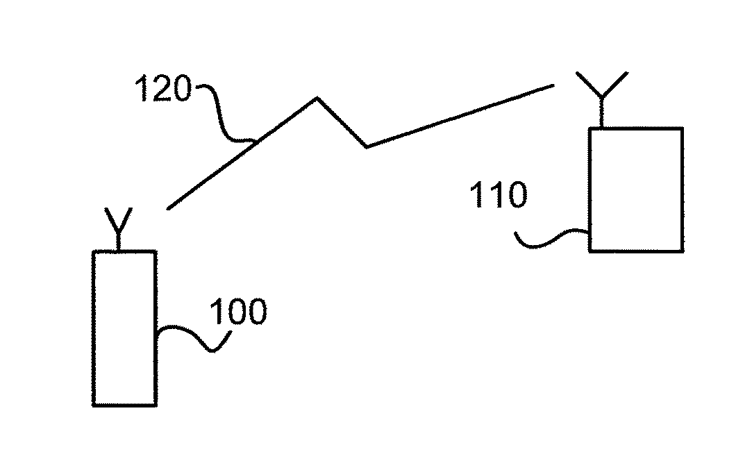
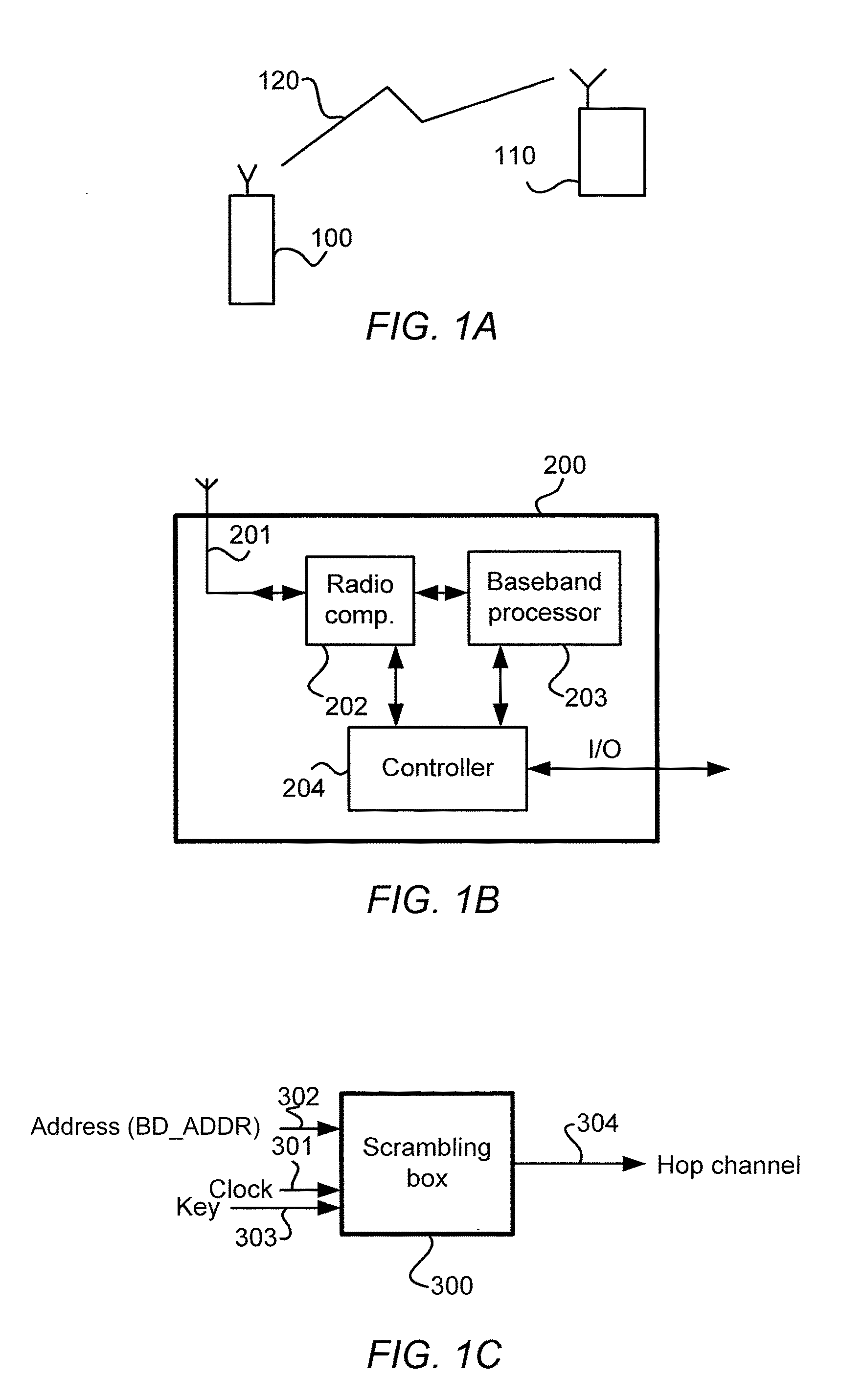
[0057]During fast recovery, the time elapsed since the previous or last synchronization between master unit 100 and slave unit 110 is still sufficiently small (a couple of minutes up to e.g. maximum 30 minutes) to be able to predict the timing in the both units 100, 110 (see FIG. 1). The former slave unit 110 (e.g. a headset or a watch) enters a recovery scan state; the former master unit 100 (e.g. a mobile phone) enters a recovery page state. Important to mention is that both these states may be low duty cycle states (in contrast to the conventional page state in Bluetooth).

[0058]1. Fast Recovery Scan

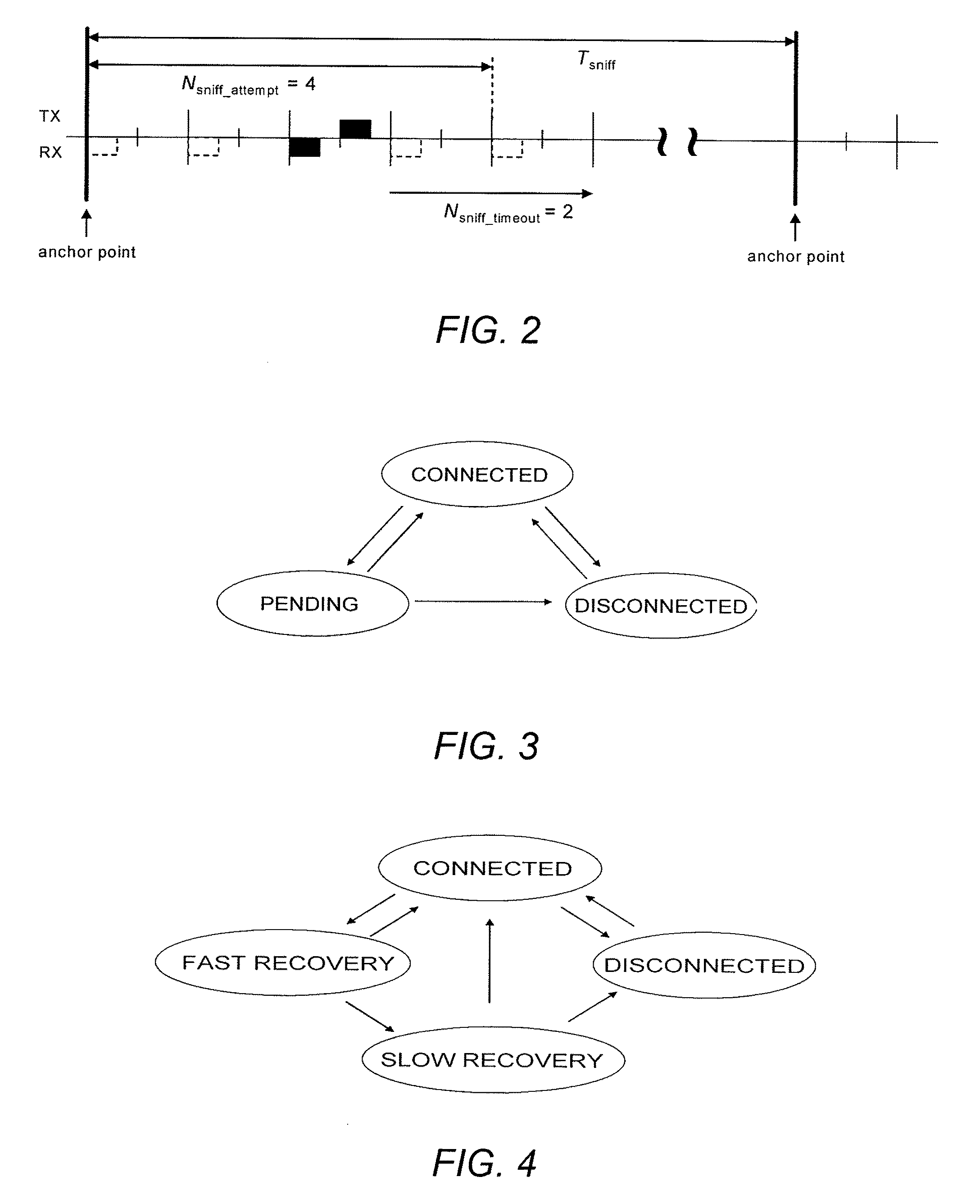
[0059]When a loss of link 120 (see FIG. 1) has been detected, the former slave unit 110 enters the fast recovery scan state. The initial timing of the scan window may be based on the anchor point timing experienced during sniff. That is, the center of the scan window may be placed at the former anchor point, see FIG. 5 which illustrates a timing diagram of the fast r...

second embodiment

B. Second Embodiment

[0091]During fast recovery, the time elapsed since the previous or last synchronization is still sufficiently small (a couple of minutes up to e.g. maximum 30 minutes) to be able to predict the timing in the both units 100, 110 (see FIG. 1). The former slave unit 110 (e.g. a headset or a watch) enters a recovery scan state; the former master unit 100 (e.g. a mobile phone) enters a recovery page state. Important to mention is that both these states are low duty cycle states (in contrast to the conventional page state in Bluetooth).

[0092]1. Fast Recovery Scan

[0093]When a loss of link 120 (see FIG. 1) has been detected, the former slave unit 110 enters the fast recovery scan state. The initial timing of the scan window may be based on the anchor point timing experienced during sniff. That is, the center of the scan window may be placed at the former anchor point, see FIG. 14 which illustrates a timing diagram of the fast recovery scan window. The scan window may hav...


PUM


Abstract

Systems and methods may include a master device. The master device may include a wake-up transmitter to send a wake-up message to a slave device to wake-up the slave device. The master device may also include a short-range transmitter to communicate with the slave device once the slave device has been woken up. The master device may be a mobile phone that communicates with the slave device (e.g., Bluetooth accessory devices) over a Bluetooth network.

Description

CROSS REFERENCE TO RELATED APPLICATIONS[0001]This application claims benefit of priority as a continuation-in-part to the filing date of U.S. patent application Ser. No. 12 / 501,053, as filed on Jul. 10, 2009, and as a continuation-in-part to the filing date of U.S. patent application Ser. No. 11 / 954,106, as filed on Dec. 11, 2007, both of which are incorporated herein by reference in their respective entireties.BACKGROUND[0002]Currently, short-range radio communication systems (e.g. WLAN 802.11, Bluetooth, ZigBee, Z-Wave, etc.) use a bi-directional data exchange. These systems are based on connections that are controlled by higher-layer applications. To achieve short latencies, radio receivers need to scan frequently or are locked into low-duty cycle connections. Low latency and low power are difficult to achieve simultaneously.SUMMARY OF THE INVENTION[0003]In accordance with an embodiment of the present invention, a radio system includes a master device. The master device may inclu...

Claims


Application Information

Patent Timeline
Patent Type & Authority Applications(United States)
IPC IPC(8): H04B7/00
CPCH04B5/0056H04B5/04H04W52/0235H04W84/20Y02D70/162Y02D70/142Y02D70/144Y02D70/26Y02D70/42Y02D30/70
Inventor HAARTSEN, JACOBUS CORNELISWEINANS, GEERT HENRIK
Owner SONY CORP
Why Eureka
Try Eureka