Radio Communication Method, Radio Base Station, Radio Communication Terminal and Base Station Controller

Active Publication Date: 2010-05-06
KYOCERA CORP
View PDF6 Cites 13 Cited by
  • Summary
  • Abstract
  • Description
  • Claims
  • Application Information

AI Technical Summary

Benefits of technology

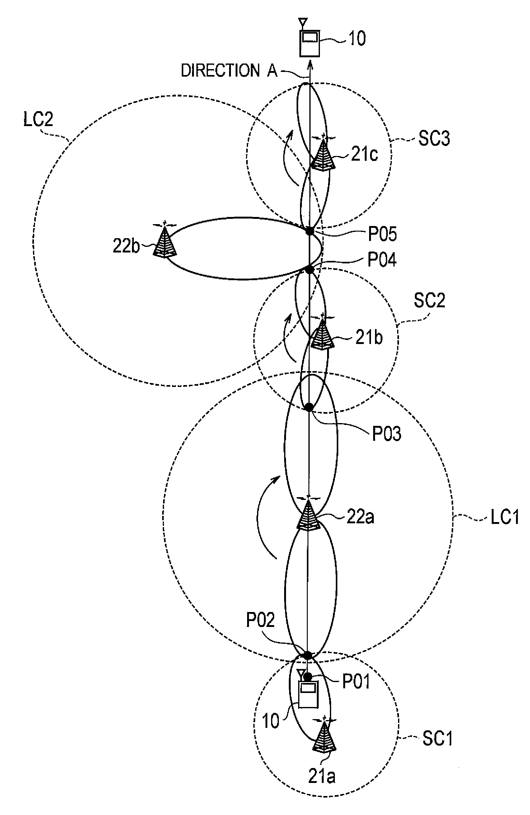
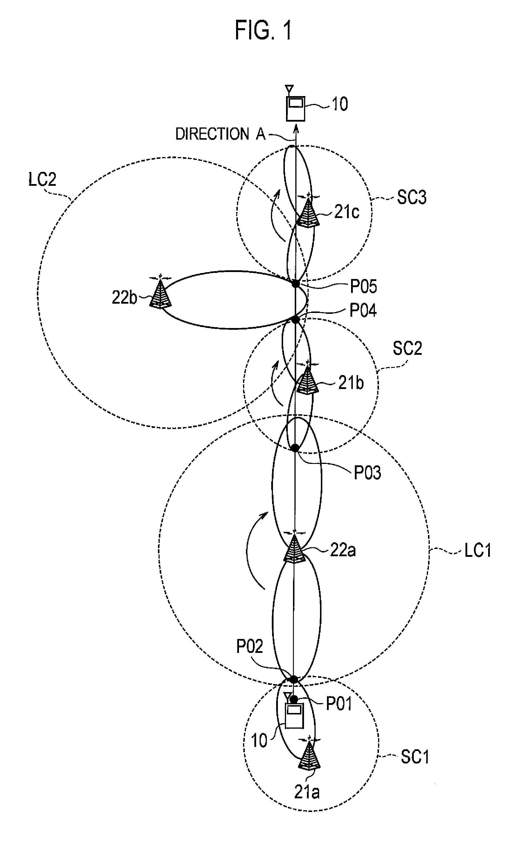
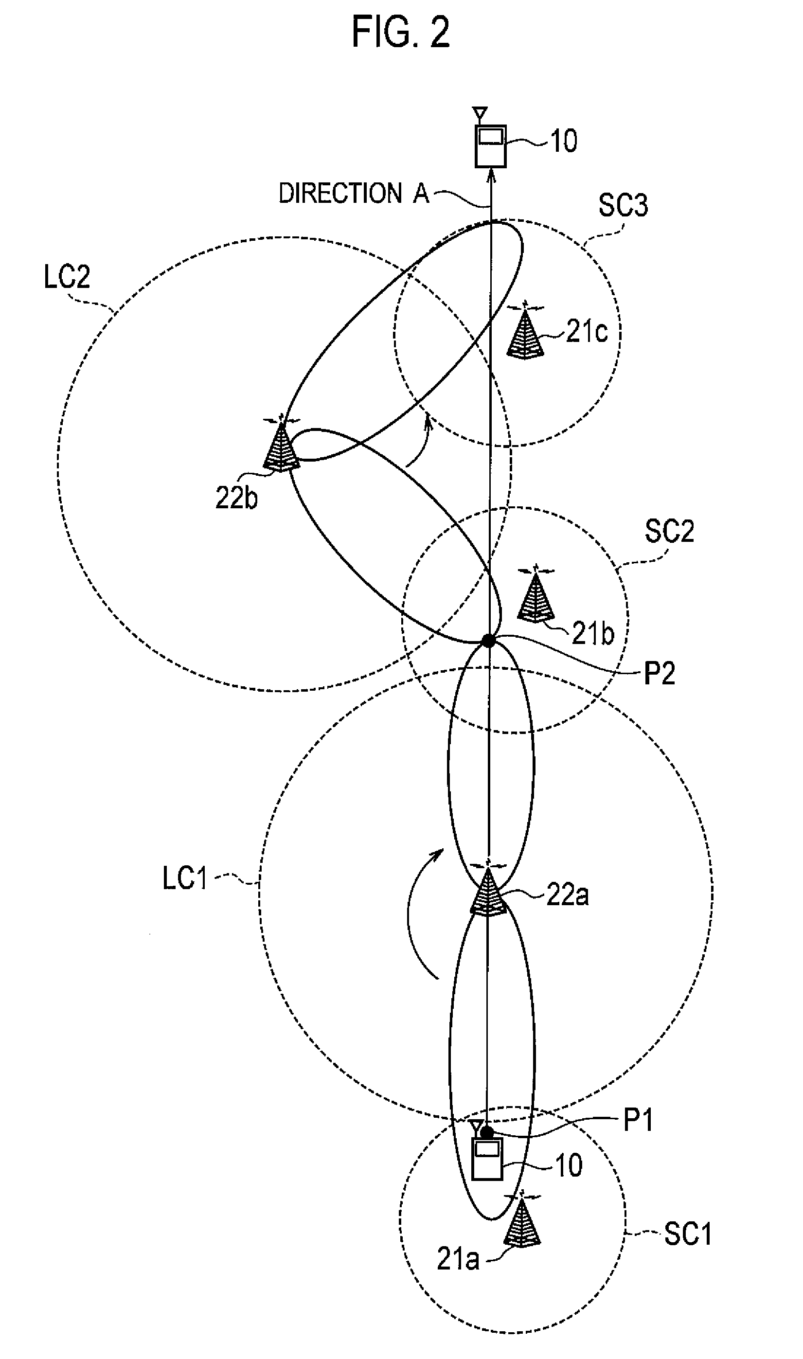
[0014]In addition, even if the moving speed of the radio communication terminal is constant, the tracking speed of a directional beam from a small cell base station, for example, is faster than the tracking speed of a directional beam from a large cell base station. Thus, when the radio communication terminal moves at high speed, this easily leads to a problem of deterioration of a signal due to a tracking error of the directional beam from the small cell base station.
[0029]According to the present invention, in the radio communication system in which the first radio base station is located adjacent to the second radio base station comprising the adaptive array antenna, it is possible to provide a radio communication method, a radio base station, a radio communication terminal, and a base station controller that can perform handovers appropriately, reduce the frequency of performing handovers, and improve communication quality even when the radio communication terminal moves at high speed.

Problems solved by technology

Consequently, there is a problem that overhead due to frequent handovers is apt to increase the processing load of a network or reduce the transmission rate.
Thus, when moving at high speed, the radio communication terminal cannot properly establish connection with a radio base station to which the radio communication terminal is to be handed over, thereby causing a problem of disconnection of communications.
Thus, when the radio communication terminal moves at high speed, this easily leads to a problem of deterioration of a signal due to a tracking error of the directional beam from the small cell base station.

Method used


Image

  • Radio Communication Method, Radio Base Station, Radio Communication Terminal and Base Station Controller
  • Radio Communication Method, Radio Base Station, Radio Communication Terminal and Base Station Controller
  • Radio Communication Method, Radio Base Station, Radio Communication Terminal and Base Station Controller

Examples


example of modification

[0151]Note that, in the communication system and the communication method according to the embodiment, it is described that the small cell base station 21 and the large cell base station 22 that operate as requesting base stations include the controller 213 having the moving speed acquisition unit 2131 and the directional beam radiation requesting unit 2132.

[0152]However, the present invention may not be limited to such the configuration. Separate from the small cell base station 21 and the large cell base station 22 that operate as the requesting base stations, a communication controller (a base station controller) having the moving speed acquisition unit 2131 and the directional beam radiation requesting unit 2132 may be provided on the network. Moreover, such the communication controller (the base station controller) may be provided in other device (radio line control station (RNC), for example) on the network.

Other Embodiments

[0153]Although one example of the present invention i...


PUM


Abstract

The present invention is a radio communication method using a first radio base station and a second radio base station located adjacent to the first radio base station and including an adaptive array antenna for radiating a dynamic directional beam, the method including the steps of: acquiring moving speed of a radio communication terminal located in a cell formed by the first radio base station; requesting the second radio base station to radiate the directional beam in a direction of the cell formed by the first radio base station when the moving speed is equal to or more than a predetermined threshold; and accommodating the radio communication terminal in the second radio base station that has transmitted the directional beam in response to the request.

Description

TECHNICAL FIELD[0001]The present invention relates to a radio communication method, a radio base station, a radio communication terminal, and a base station controller using an adaptive array antenna that radiates dynamic directional beam.BACKGROUND ART[0002]Conventionally, in a radio communication system, a radio communication terminal (a mobile phone terminal, for example) receives base station reference signals (pilot signals or the like, for example) from multiple radio base stations, and is accommodated in a radio base station having the strongest received power of the base station reference signal.[0003]In addition, the radio communication terminal is configured to be handed over, when moving, to a radio base station with the strongest received power of the base station reference signal among radio base stations in the periphery, on the basis of peripheral radio station information acquired from a radio base station in which the radio communication terminal is currently accomm...

Claims


Application Information

Patent Timeline
IPC IPC(8): H04W4/00H04W16/28
CPCH04B7/022H04W16/28H04B7/0617H04B7/086H04B7/10H04W52/42
Inventor JOKO, SHINGOTODA, TAKESHINAKAYAMA, TAKU
Owner KYOCERA CORP
Why Eureka
Try Eureka